
Page 438 - Mechatronics for Safety, Security and Dependability in a New Era
P. 438
Ch85-I044963.fm Page 422 Monday, August 7, 2006 11:32 AM
Ch85-I044963.fm
422
422 Page 422 Monday, August 7,2006 11:32 AM
STRUCTURE OF W AND MACHINING PROCESS
The inner and outer walls of the ITER-Vacuum Vessel (VV) are made of 60mm thick stainless steel
316L and are welded together not directly, but with an intermediate so-called "splice plate" inserted
between the sectors to be joined. This splice plate has two important functions; to allow access to bolt
together the thermal shield between the VV and coils, and to compensate for mismatch between
adjacent sectors to give a good fit-up of the sector-sector butt weld. The robot end-effector will have to
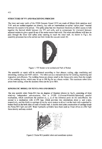
pass through the inner wall splice plate opening to reach the outer wall. As shown in Fig.l, the
assembly processes has to be carried out from inside the vacuum vessel [4].
Figure 1: VV Sector to be welded and Path of Robot
The assembly or repair will be performed according to four phases: cutting, edge machining and
smoothing, welding and NDT control. The robot acts as a transport device for welding, machining and
inspection end-effectors. The welding forces are always small so the forces only come from the weight
of the welding device, which may be up to 200 Kg for an e-beam welder. The maximum robot force
arises from cutting, when the dynamic force can be up to 3KN.
KINEMATIC MODEL OF PENTA-WH AND DESIGN
The new parallel robot Penta-WH has six degrees of freedom (shown in Fig.2), consisting of three
relatively independent sub-structures. One is 3-UPS (Universal-Prismatic-Spherical) parallel
mechanism, which contributes the position (x, y, z) of the reference point on the end-effector, the
second is a mechanism with 2-UPS legs, which provides two orientations about x- and y-axis,
respectively, and the third is a carriage driven by servo motors to drive it on the track rails supported by
beams fixed on the both sides of seam of inside wall. A double steel plate construction of carriage keeps
the Penta-WH light and stiff. Water hydraulic cylinders have been used as linear drives to offer high
force density and easy control.
Figure 2: Penta-WH parallel robot and coordinate system