
Page 201 - Methods For Monitoring And Diagnosing The Efficiency Of Catalytic Converters A Patent - oriented Survey
P. 201
Suzuki Motor Corporation 183
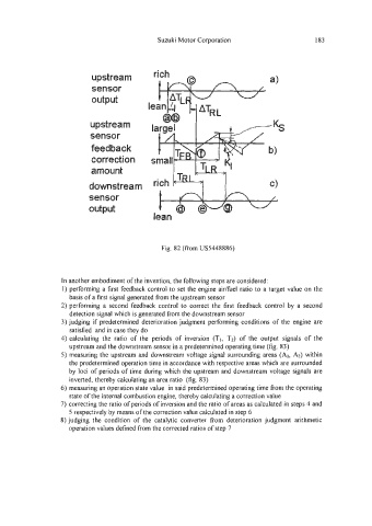
upstream
sensor
output
upstream
sensor
feedback
correction
amount
downstream
sensor
output -
lean -
Fig. 82 (from US5448886)
In another embodiment of the invention, the following steps are considered:
1) performing a first feedback control to set the engine aidfuel ratio to a target value on the
basis of a first signal generated from the upstream sensor
2) performing a second feedback control to correct the first feedback control by a second
detection signal which is generated from the downstream sensor
3) judging if predetermined deterioration judgment performing conditions of the engine are
satisfied and in case they do
4) calculating the ratio of the periods of inversion (TI, T2) of the output signals of the
upstream and the downstream sensor in a predetermined operating time (fig. 83)
5) measuring the upstream and downstream voltage signal surrounding areas (AI, A$ within
the predetermined operation time in accordance with respective areas which are surrounded
by loci of periods of time during which the upstream and downstream voltage signals are
inverted, thereby calculating an area ratio (fig. 83)
6) measuring an operation state value in said predetermined operating time from the operating
state of the internal combustion engine, thereby calculating a correction value
7) correcting the ratio of periods of inversion and the ratio of areas as calculated in steps 4 and
5 respectively by means of the correction value calculated in step 6
8) judging the condition of the catalytic converter from deterioration judgment arithmetic
operation values defined from the corrected ratios of step 7