
Page 291 - Methods For Monitoring And Diagnosing The Efficiency Of Catalytic Converters A Patent - oriented Survey
P. 291
Ford Motor Co. - Ford France SA - Ford Werke AG - Ford Motor Co. Ltd. 273
1
0.9
0.8
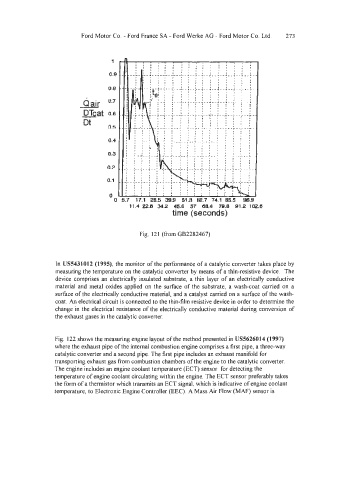
Q air 0.7
mat 0.6
Dt
0.5
0.4
0.3
n.3
0.1
OO
11.4 22.8 34.2 45.6 57 60.4 Tg.a 91.2 i(lz.6
time (seconds)
Fig. I21 (from GB2282467)
In US5431012 (1995). the monitor of the performance of a catalytic converter takes place by
measuring the temperature on the catalytic converter by means of a thin-resistive device. The
device comprises an electrically insulated substrate, a thin layer of an electrically conductive
material and metal oxides applied on the surface of the substrate, a wash-coat carried on a
surface of the electrically conductive material, and a catalyst carried on a surface of the wash-
coat. An electrical circuit is connected to the thin-film resistive device in order to determine the
change in the electrical resistance of the electrically conductive material during conversion of
the exhaust gases in the catalytic converter.
Fig. 122 shows the measuring engine layout of the method presented in US5626014 (1997)
where the exhaust pipe of the internal combustion engine comprises a first pipe, a three-way
catalytic converter and a second pipe. The first pipe includes an exhaust manifold for
transporting exhaust gas from combustion chambers of the engine to the catalytic converter.
The engine includes an engine coolant temperature (ECT) sensor for detecting the
temperature of engine coolant circulating within the engine. The ECT sensor preferably takes
the form of a thermistor which transmits an ECT signal, which is indicative of engine coolant
temperature, to Electronic Engine Controller (EEC). A Mass Air Flow (MAF) sensor is