
Page 25 -
P. 25
14 1 From Optical MEMS to Micromechanical Photonics
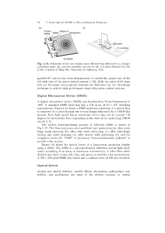
(a) (b)
Torsion Hinge pin
spring Staple Spring-latch
Side-latch
Si substrate
Substrate
Fig. 1.15. Schematic of the out-of-plane micro-Fresnel lens fabricated on a hinged
polysilicon plate (a), and the assembly process for the 3-D micro-Fresnel lens (b)
[1.38]. Courtesy of Ming Wu, University of California, USA
parallel 45 mirrors has been demonstrated to match the optical axis of the
◦
LD with that of the micro-optical element [1.38]. Both the micro-XYZ stage
and the free-space micro-optical elements are fabricated by the microhinge
technique to achieve high-performance single-chip micro-optical systems.
Digital Micromirror Device (DMD)
A digital micromirror device (DMD) was developed by Texas Instruments in
6
1987. A standard DMD microchip has a 2-D array of 0.4 × 10 switching
micromirrors. Figure 1.16 shows a DMD structure consisting of a mirror that
is connected to a yoke through two torsion hinges fabricated by a CMOS-like
process. Each light switch has an aluminum mirror that can be rotated ±10
degrees by electrostatic force depending on the state of the underlying CMOS
circuit [1.5].
The surface micromachiningprocess to fabricate DMD is shown in
Fig. 1.17. The illustrations are after sacrificial layer patterning (a), after oxide
hinge mask pattering (b), after yoke oxide patterning (c), after yoke/hinge
etchingand oxide stripping(d), after mirror oxide patterning(e), and the
completed device (f). “CMP” in (a) means “chemomechanically polished” to
provide a flat surface.
Figure 1.18 shows the optical layout of a large-screen projection display
usinga DMD. The DMD is a micromechanical reflective spatial light mod-
ulator consistingof an array of aluminum micromirrors. A color filter wheel
divided into three colors; red, blue, and green, is used for color presentation.
A 768 × 576 pixel DMD was tested and a contrast ratio of 100 was reported.
Optical Switch
Analogand digital switches, tunable filters, attenuators, polarization con-
trollers, and modulators are some of the devices required in optical