
Page 210 - A Practical Guide from Design Planning to Manufacturing
P. 210
Logic Design 183
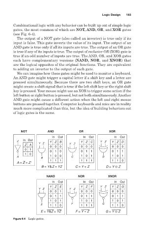
Combinational logic with any behavior can be built up out of simple logic
gates, the most common of which are NOT, AND, OR, and XOR gates
(see Fig. 6-4).
The output of a NOT gate (also called an inverter) is true only if its
input is false. This gate inverts the value of its input. The output of an
AND gate is true only if all its inputs are true. The output of an OR gate
is true if any of its inputs is true. The output of exclusive-OR (XOR) gate is
true if an odd number of inputs are true. The AND, OR, and XOR gates
each have complementary versions (NAND, NOR, and XNOR) that
are the logical opposites of the original functions. They are equivalent
to adding an inverter to the output of each gate.
We can imagine how these gates might be used to monitor a keyboard.
An AND gate might trigger a capital letter if a shift key and a letter are
pressed simultaneously. Because there are two shift keys, an OR gate
might create a shift signal that is true if the left shift key or the right shift
key is pressed. Your mouse might use an XOR to trigger some action if the
left button or right button is pressed, but not both simultaneously. Another
AND gate might cause a different action when the left and right mouse
buttons are pressed together. Computer keyboards and mice are in reality
much more complicated than this, but the idea of building behaviors out
of logic gates is the same.
NOT AND OR XOR
In Out In Out In Out
Z In Out Y Z B Y Z C Y Z Y Z D
YZ Y Z
Z A
0 0 0 0 0 0 0 0 0
0 1
0 1 0 0 1 1 0 1 1
1 0
A 1 0 0 C 1 0 1 D 1 0 1
B
1 1 1 1 1 1 1 1 0
A = Z = Z ′
B = Y&Z = YZ C = Y + Z D = Y ⊕ Z
NAND NOR XNOR
In Out In Out In Out
Y Z E Y Z F Y Z Y Z G
YZ Y Z
0 0 1 0 0 0 0 0 0
0 1 1 0 1 1 0 1 1
1 0 1 1 0 1 1 0 1
E 1 1 0 F 1 1 1 G 1 1 0
E = Y&Z = YZ F = Y + Z G = Y ⊕ Z
Figure 6-4 Logic gates.