
Page 219 - A Practical Guide from Design Planning to Manufacturing
P. 219
192 Chapter Six
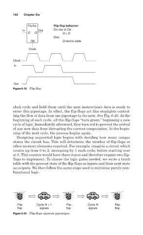
Flip-flop Flip-flop behavior:
In Out On rise of Clk
D Q Q = D
Else
Clk Q retains state
Clock
Clock
In
Out
Figure 6-19 Flip-flop.
clock cycle and hold them until the next instruction’s data is ready to
enter this pipestage. In effect, the flip-flops act like stoplights control-
ling the flow of data from one pipestage to the next. See Fig. 6-20. At the
beginning of each cycle, all the flip-flops “turn green,” beginning a new
cycle of logic. Immediately afterward, they turn red to prevent the arrival
of any new data from disrupting the current computation. At the begin-
ning of the next cycle, the process begins again.
Designing sequential logic begins with deciding how many unique
states the circuit has. This will determine the number of flip-flops or
other memory elements required. For example, imagine a circuit which
counts up from 0 to 2, increasing by 1 each cycle, before starting over
at 0. This counter would have three states and therefore require two flip-
flops to implement. To choose the logic gates needed, we write a truth
table with the present state of the flip-flops as inputs and their next state
as outputs. We then follow the same steps used to minimize purely com-
binational logic.
Flip- Cycle N + 1 Flip- Cycle N Flip-
flop signals flop signals flop
Figure 6-20 Flip-flops separate pipestages.