
Page 288 - Microsensors, MEMS and Smart Devices - Gardner Varadhan and Awadelkarim
P. 288
268 MICROSENSORS
There is considerable interest in silicon gyroscopes in the defence industries for control-
ling missiles, but low-cost commercial devices for nonmilitary applications (e.g. automo-
tive) are now appearing.
8.4.8 Flow Microsensors
The measurement of the flow rate of a gas (or liquid) is important in a number of
different fields from automotive and aerospace to the chemical industries. For example, it
is important to know the amount of fuel flowing into an engine or domestic gas supplied to
boilers in homes. Indeed, there are a number of traditional ways to measure flow directly
(e.g. a rotating vane) and indirectly through the differential pressure (orifice plate, Venturi
tube, and Pilot tube). Here, we are interested in the measurement of flow using novel
micromechanical sensors. One possible method is to use an ultrasonic technique such as
a SAW device but, as these are covered elsewhere, we will focus here on other types of
micromechanical devices.
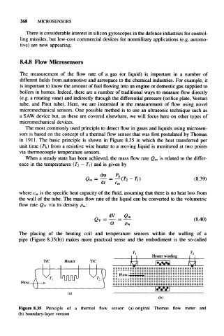
The most commonly used principle to detect flow in gases and liquids using microsen-
sors is based on the concepl of a ihermal flow sensor lhat was first postulated by Thomas
in 1911. The basic principle is shown in Figure 8.35 in which the heat transferred per
unit time (P h) from a resistive wire heater to a moving liquid is monitored at two points
via ihermocouple temperature sensors.
When a steady state has been achieved, the mass flow rate Q m is related to the differ-
ence in the temperalures (T 2 — T 1) and is given by
G« = ^ = —(Ti-r,) (8.39)
dr c m
is the specific heat capacity of the fluid, assuming that there is no heat loss from
where c m
the wall of the tube. The mass flow rate of the liquid can be converted to the volumetric
flow rate Qv via its density p m:
Qv = — = — (8.40)
The placing of the heating coil and temperature sensors within the walling of a
pipe (Figure 8.35(b)) makes more practical sense and the embodiment is the so-called
I | Heater winding
T/C Heater T/C H
= = Flow
U
v
v
U
A r, UUU T 2y
Flow-
(a)
(b)
Figure 8.35 Principle of a thermal flow sensor: (a) original Thomas flow meter and
(b) boundary-layer version