Page 267 - Modeling of Chemical Kinetics and Reactor Design
P. 267

Industrial and Laboratory Reactors  237


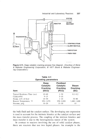
                              Figure 4-11. Deep catalytic cracking process flow diagram. (Courtesy of Stone
                              & Webster Engineering Corporation, © 1977 Stone & Webster  Engineer-
                              ing Corporation.)


                                                          Table 4-1
                                                   Operating parameters
                                                           Deep         Fluidized
                                                         Catalytic      Catalytic      Steam
                                                         Cracking       Cracking      Cracking
                              Item                         (DCC)         (FCC)          (SC)
                              Typical Residence Time (sec)  10–60         1–30         0.1–0.2
                              Catalyst/Oil                  9–15          5–10
                              Steam, wt% of feed           10–30          1–10          30–80
                              Reactor Temperature, °F     950–1,070     950–1,020    1,400–1,600
                              Pressure, psig               10–20         15–30           15


                              the bulk fluid and the catalyst surface. The developing rate expression
                              is used to account for the intrinsic kinetics at the catalyst surface and
                              the mass transfer process. The coupling of the intrinsic kinetics and
                              mass transfer is due to the heterogeneous nature of the system.
                                In contrast to reactors involving the use of solid catalyst phases,
                              there are reactors that use two liquid phases.  An example is the
   262   263   264   265   266   267   268   269   270   271   272