
Page 189 - Modern Control Systems
P. 189
Section 3.2 The State Variables of a Dynamic System 163
Input signals Output signals
FIGURE 3.1 it lit) ^ v,(r)
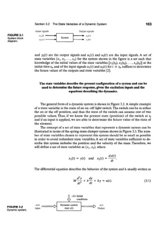
System block System
diagram.
and y 2(t) are the output signals and U\(i) and u 2(t) are the input signals. A set of
state variables (xi, x 2,..,, x„) for the system shown in the figure is a set such that
knowledge of the initial values of the state variables [x 1(f 0), x 2(t 0), . • •, x n(h)] at the
initial time / 0, and of the input signals Ui(t) and u 2(t) for t ^ t 0, suffices to determine
the future values of the outputs and state variables [2].
The state variables describe the present configuration of a system and can be
used to determine the future response, given the excitation inputs and the
equations describing the dynamics.
The general form of a dynamic system is shown in Figure 3.2. A simple example
of a state variable is the state of an on-off light switch. The switch can be in either
the on or the off position, and thus the state of the switch can assume one of two
possible values. Thus, if we know the present state (position) of the switch at t 0
and if an input is applied, we are able to determine the future value of the state of
the element.
The concept of a set of state variables that represent a dynamic system can be
illustrated in terms of the spring-mass-damper system shown in Figure 3.3. The num-
ber of state variables chosen to represent this system should be as small as possible
in order to avoid redundant state variables. A set of state variables sufficient to de-
scribe this system includes the position and the velocity of the mass. Therefore, we
will define a set of state variables as (x h x 2), where
dyjt)
*i(0 = y(t) and x 2(t) =
dt '
The differential equation describes the behavior of the system and is usually written as
2
. d y dy
M , 2 + b— + ky = u(t). (3.1)
y
w
dt -" dt
A v(0) Initial
conditions
u(t) Dynamic system -N> v(')
FIGURE 3.2 Input ^> state x{t) ~^ Output
Dynamic system.