Page 184 - Modern Control Systems
P. 184

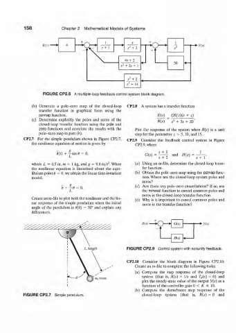
158             Chapter 2  Mathematical  Models of Systems


                                     +  r~\    1           s
                    Ris)  •                                        \r                  *•  ¥(s)
                                     ~i\.     s+  1      s 2  +  2  +  •      s 2

                                                        4s+  2
                                                                              50
                                                      s 2  +  2s + 1

                                                         s 2  +  2
                                                         ,9 3  +  14
                    FIGURE CP2.6  A multiple-loop feedback control system block diagram.


               (b)  Generate  a  pole-zero  map  of  the  closed-loop  CP2.8  A system has a transfer  function
                  transfer  function  in  graphical  form  using  the
                  pzmap  function.                                    X(s)   (20/z)(s  +  z)
               (c)  Determine  explicitly  the  poles  and  zeros  of  the  B{s)  ~  s 2  + 3s  +  20"
                  closed-loop  transfer  function  using  the  pole  and
                  zero  functions  and  correlate  the  results  with  the  Plot  the  response  of  the  system  when  R(s)  is  a  unit
                  pole-zero map in part (b).                 step for the parameter  z  =  5,10,  and 15.
           CP2.7  For  the  simple pendulum  shown  in Figure  CP2.7,  CP2.9  Consider  the  feedback  control  system  in  Figure
               the nonlinear equation  of motion is given by   CP2.9, where

                          0(0  +  ™ sin 6  0,                    G(s)  =  ^ ^  and  H(s)
                                                                       s  + 2          s+  1
               where L  =  0.5 m, m  =  1 kg, and g  =  9.8 m/s~. When   (a)  Using  an m-file, determine  the closed-loop trans-
               the  nonlinear  equation  is linearized  about  the  equi-  fer  function.
               librium point 6 = 0, we obtain the linear time-invariant   (b)  Obtain  the pole-zero map  using the pzmap  func-
               model,                                           tion. Where are the closed-loop system poles and
                                                                zeros?
                                                             (c)  Are  there  any pole-zero  cancellations?  If so, use
                            0  +  j6  0.
                                                                the minreal function  to cancel common poles and
                                                                zeros in the closed-loop transfer  function.
               Create an m-file to plot both the nonlinear and the lin-  (d)  Why  is it important  to cancel common  poles  and
               ear response  of the  simple pendulum  when the  initial  zeros  in the transfer  function?
               angle  of the pendulum  is 0(0)  =  30° and  explain  any
               differences.

                                                                lite)  •      G(s)      •*•  Y(s)
            ^   ^    ^    ^    .   ^    ^    ^

                                                                              H(s)  4

                                                         FIGURE CP2.9  Control system with nonunity feedback.

                                                         CP2.10  Consider  the  block  diagram  in  Figure  CP2.10.
                                                             Create  an m-file to complete the following tasks:
                                                            (a)  Compute  the  step  response  of  the  closed-loop
                                                                system  (that  is,  R(s)  =  Vs  and  7",,(i)  =  0)  and
                                                                plot the steady-state  value  of the output  Y(s)  as a
                                                                function  of the controller  gain 0  <  K  s  10.
                                                             (b)  Compute  the  disturbance  step  response  of  the
           FIGURE CP2.7  Simple pendulum.                       closed-loop  system  (that  is,  R(s)  = 0  and
   179   180   181   182   183   184   185   186   187   188   189