Page 182 - Modern Control Systems
P. 182

156              Chapter  2  Mathematical  Models  of  Systems


                            W.v)                                          -*•  Y(s)


            FIGURE  DP2.1
            Selection of transfer             ff.
            functions.


                            Reference
                            J T                                                    A / W
                                                                       «1       a
                       <t>M.             ©20A     f:                            b  v>           -o  +

                                                                       R 2
                                                                                                 "<
                                                            "1              C
            FIGURE  DP2.2  Television beam circuit.

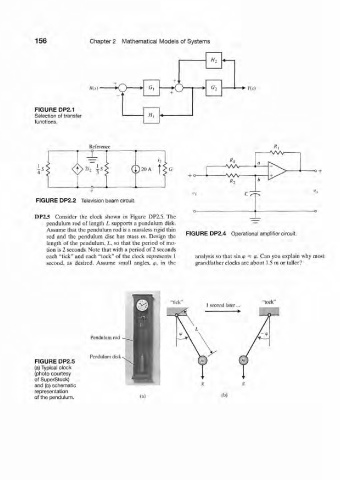
            DP2.5  Consider  the  clock  shown  in  Figure  DP2.5. The
               pendulum  rod  of length  L  supports  a pendulum  disk.
               Assume  that the pendulum rod  is a massless rigid thin
               rod  and  the  pendulum  disc  has  mass  m.  Design  the  FIGURE  DP2.4  Operational amplifier circuit.
               length  of the pendulum, L, so that the  period  of mo-
               tion  is 2 seconds. Note that  with a period  of 2 seconds
               each "tick" and  each "tock"  of the  clock represents 1   analysis so that  sin <p  w (p.  Can  you  explain  why most
               second,  as  desired.  Assume  small  angles,  <p,  in  the  grandfather  clocks are about  1.5 m or taller?


                             Pendulum rod


                             Pendulum disk ^.
            FIGURE  DP2.5
            (a) Typical clock
            (photo courtesy
            of SuperStock)
            and (b) schematic
            representation
            of the pendulum.
   177   178   179   180   181   182   183   184   185   186   187