
Page 178 - Modern Control Systems
P. 178
152 Chapter 2 Mathematical Models of Systems
Amplifier
Valve
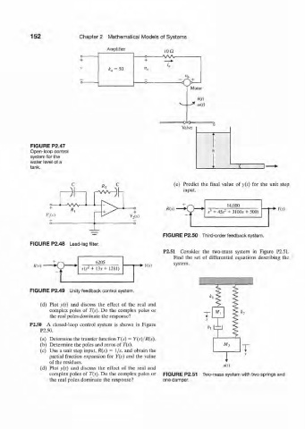
FIGURE P2.47
Open-loop control
system for the
water level of a
tank.
(e) Predict the final value of y(t) for the unit step
)l—i r^Mh input.
- A A A r 14,000
R(s) ,! + 45^ + 31005 + 500) •*• i'(-v)
3
ViM V 2(s)
FIGURE P2.50 Third-order feedback system.
FIGURE P2.48 Lead-lag filter.
P2.51 Consider the two-mass system in Figure P2.51.
Find the set of differential equations describing the
6205 system.
tf(.v) ' •*• Y(s)
s(s-+ 13*+ 1281)
FIGURE P2.49 Unity feedback control system.
(d) Plot y(t) and discuss the effect of the real and
complex poles of T(s). Do the complex poles or
the real poles dominate the response?
P2.50 A closed-loop control system is shown in Figure
P2.50.
(a) Determine the transfer function T(s) = Y(s)/R(s).
(b) Determine the poles and zeros of T(s).
(c) Use a unit step input, R(s) = l/s, and obtain the
partial fraction expansion for Y(s) and the value
of the residues.
(d) Plot y(() and discuss the effect of the real and
complex poles of T(s). Do the complex poles or FIGURE P2.51 Two-mass system with two springs and
the real poles dominate the response? one damper.