
Page 176 - Modern Control Systems
P. 176
150 Chapter 2 Mathematical Models of Systems
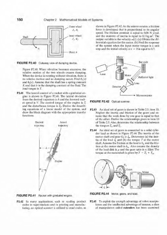
. Outer wheel shown in Figure P2.42. As the mirror rotates, a friction
force is developed that is proportional to its angular
speed. The friction constant is equal to 0.06 N s/rad,
2
. Inner wheel and the moment of inertia is equal to 0.1 kg m . The
Shaft /
./,,0, output variable is the velocity cu(r). (a) Obtain the dif-
% ferential equation for the motor, (b) Find the response
of the system when the input motor torque is a unit
step and the initial velocity at J = 0 is equal to 0.7.
Fluid, b
Mirror
FIGURE P2.40 Cutaway view of damping device. Bar code
Figure P2.40. When vibration becomes excessive, the
relative motion of the two wheels creates damping.
When the device is rotating without vibration, there is
no relative motion and no damping occurs. Find B^s) Reflected light
and 02(s). Assume that the shaft has a spring constant
K and that b is the damping constant of the fluid. The
load torque is T.
P2.41 The lateral control of a rocket with a gimbaled en-
gine is shown in Figure P2.41. The lateral deviation Microcomputer
from the desired trajectory is h and the forward rock-
et speed is V. The control torque of the engine is £. FIGURE P2.42 Optical scanner.
and the disturbance torque is T tf. Derive the describ-
ing equations of a linear model of the system, and P2.43 An ideal set of gears is shown in Table 2.5, item 10.
draw the block diagram with the appropriate transfer Neglect the inertia and friction of the gears and as-
functions. sume that the work done by one gear is equal to that
of the other. Derive the relationships given in item 10
Desired Aclua] of Table 2.5. Also, determine the relationship between
trajectory trajectory the torques T m and T L.
P2.44 An ideal set of gears is connected to a solid cylin-
der load as shown in Figure P2.44. The inertia of the
motor shaft and gear G 2 is J m. Determine (a) the iner-
tia of the load J L and (b) the torque T at the motor
shaft. Assume the friction at the load is b L and the fric-
tion at the motor shaft is b m. Also assume the density
of the load disk is p and the gear ratio is n. Hint: The
torque at the motorshaft is given by T = T\ + T m.
Engine
FIGURE P2.44 Motor, gears, and load.
FIGURE P2.41 Rocket with gimbaled engine.
P2.42 In many applications, such as reading product P2.45 To exploit the strength advantage of robot manipu-
codes in supermarkets and in printing and manufac- lators and the intellectual advantage of humans, a class
turing, an optical scanner is utilized to read codes, as of manipulators called extenders has been examined