
Page 173 - Modern Control Systems
P. 173
Problems 147
relationship between the air gap z and the controlling input current i controls the torque with negligible fric-
current near the equilibrium condition. tion. Assume the beam may be balanced near the hor-
izontal (<f> = 0); therefore, we have a small deviation
of <f>. Find the transfer function X(s)/I(s). and draw a
block diagram illustrating the transfer function show-
ing ¢(5), X(s), and T(s).
P2.30 The measurement or sensor element in a feedback
system is important to the accuracy of the system [6].
The dynamic response of the sensor is important.
Most sensor elements possess a transfer function
T.S + 1
Suppose that a position-sensing photo detector has
T = 4,us and 0.999 < k < 1.001. Obtain the step re-
sponse of the system, and find the k resulting in the
fastest response—that is, the fastest time to reach 98%
of the final value.
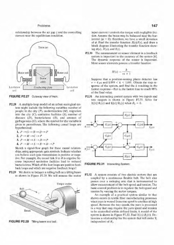
FIGURE P2.27 Cutaway view of train. P2.31 An interacting control system with two inputs and
two outputs is shown in Figure P2.31. Solve for
Y t(s)/Ri(s) and Y 2(s)/R 1(s) when R 2 = 0.
P2.28 A multiple-loop model of an urban ecological sys-
tem might include the following variables: number of
people in the city (P), modernization (M), migration
into the city (C), sanitation facilities (S), number of
diseases (D), bacteria/area (B), and amount of
garbage/area (G), where the symbol for the variable is
given in parentheses. The following causal loops are
hypothesized: KM Yds)
1. P^G^B^D-^P
2. P-*M^C-^P
3. P-*-M—S-*D-*P
4. P^>M-*S^B-*D^>P
Sketch a signal-flow graph for these causal relation- ffji*) . v i—: i i :—i r,(.v)
ships, using appropriate gain symbols. Indicate whether
you believe each gain transmission is positive or nega-
tive. For example, the causal link S to B is negative be-
cause improved sanitation facilities lead to reduced
bacteria/area. Which of the four loops are positive feed- FIGURE P2.31 Interacting System.
back loops and which are negative feedback loops?
P2.29 We desire to balance a rolling ball on a tilting beam
as shown in Figure P2.29. We will assume the motor P2.32 A system consists of two electric motors that are
coupled by a continuous flexible belt. The belt also
passes over a swinging arm that is instrumented to
Torque motor allow measurement of the belt speed and tension. The
basic control problem is to regulate the belt speed and
tension by varying the motor torques.
An example of a practical system similar to that
shown occurs in textile fiber manufacturing processes
when yarn is wound from one spool to another at high
speed. Between the two spools, the yarn is processed
in a way that may require the yarn speed and tension
to be controlled within defined limits. A model of the
system is shown in Figure P2.32. Find J5(s)/i?j{5), De-
termine a relationship for the system that will make K
FIGURE P2.29 Tilting beam and ball. independent of jRj.