Page 168 - Modern Control Systems
P. 168

142              Chapter 2  Mathematical  Models of  Systems

                                                            for  the  fluid-flow  equation,  (b)  What  happens  to  the
                         .J                                 approximation  obtained  in  part  (a)  if  the  operating
                                                            point is Pi  -  P 2 =  0?
                  Force  < ; * !  L                      P2.6  Using the Laplace transformation, obtain the current
                  m   ••  >        J "                       I 2(s)  of  Problem  P2.1. Assume  that  all the  initial  cur-
                              AT,           |  v .<')       rents are zero, the initial voltage across capacitor C\ is
                                                            zero, v{t) is zero, and the initial voltage across C 2 is 10
                                                            volts.
                                                         P2.7  Obtain  the  transfer  function  of  the  differentiating
                                                            circuit shown in Figure P2.7.
                                     T>'2<'>
                              ftf 2
                                                                     1
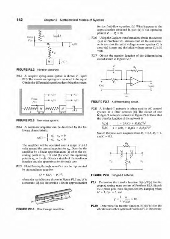
           FIGURE P2.2  Vibration absorber.
           P2.3  A  coupled  spring-mass  system  is  shown  in  Figure
               P2.3. The masses and  springs are  assumed  to  be equal.
               Obtain the differential  equations describing the system.                     +
                                                              VAs)
                                                                                            V 2[s)

                                            -»•  I'II O
                    Force       v,(r)       -*•  A',(0
                     ru)                                 FIGURE  P2.7  A differentiating circuit.
                            I
                         M   WWWH u         Hi           P2.8  A  bridged-T  network  is  often  used  in  AC  control
                   k                                        systems  as  a  filter  network  [8]. The  circuit  of  one
                                k    nzn                    bridged-T network  is shown  in Figure P2.8. Show that
                                                            the transfer  function  of the network is
           FIGURE P2.3  Two-mass system.
                                                                V&)      1  +  IR^Cs  +  RiRjpV
           P2.4  A  nonlinear  amplifier  can  be  described  by the  fol-  Kn(i')  1 +  (2«,  +  R 2)Cs  +  i?,i? 2 cV
               lowing characteristic:
                                                            Sketch the pole-zero diagram when R x  =  0.5,¾  =  1,
                              J  4                          and C  =  0.5.
                        "o(')  =
                                    «m  <  0'
                              I  4
               Tlie  amplifier  will be  operated  over  a range  of  ±0.5
               volts around  the operating point for  v in.  Describe  the  wv
               amplifier  by  a linear  approximation  (a) when  the op-
               erating  point  is  sjj,, =  0  and  (b)  when  the  operating
               point  is  w in  =  1  volt.  Obtain  a sketch  of the  nonlinear
               function  and the approximation  for each case.
           P2.5  Fluid flowing  through  an  orifice  can be represented
               by the nonlinear  equation
                                      2
                         Q  =  K(P,  -  A)" ,            FIGURE P2.8  Bridged-T network.
               where the variables are shown  in Figure P2.5 and K  is
               a  constant  [2]. (a)  Determine  a  linear  approximation  P2.9  Determine  the  transfer  function  Xi(s)/F(s)  for  the
                                                            coupled  spring-mass  system  of  Problem  P2.3. Sketch
                                                            the s-plane pole-zero  diagram  for  low damping  when
                                                            M  =  l,b/k  =  l,and

                                                                                   0.1.
                                                                       4
                                                                          2-
                                                         P2.10  Determine  the  transfer  function  Yi{s)jF(s)  for  the
           FIGURE  P2.5  Flow through an orifice.           vibration absorber system  of Problem  P2.2. Determine
   163   164   165   166   167   168   169   170   171   172   173