
Page 167 - Modern Control Systems
P. 167
Problems 141
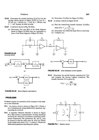
E2.28 Determine the transfer function \&(s)/V(s) for the (b) Determine Y(s)/R(s) for Figure E2.29(b).
op-amp circuit shown in Figure E2.28 [1]. Let /?j = E2.30 A system is shown in Figure E2.30.
167 kfl, R 2 = 240 kH, R 3 = 1 kH, R A = 100 kH, and
C = 1 /iF. Assume an ideal op-amp. (a) Find the closed-loop transfer function Y(s)/R(s)
E2.29 A system is shown in Fig. E2.29(a). 10
-
when G(s) = : .
(a) Determine G(s) and H(s) of the block diagram s 2 + 2s + 10
shown in Figure E2.29(b) that are equivalent to (b) Determine Y(s) when the input R(s) is a unit step.
those of the block diagram of Figure E2.29(a).
(c) Compute y(t).
3r
o—*—WV—"•
+ R,
-o +
_L ± _n
FIGURE E2.28
Op-amp circuit.
1 /?(*) • ns)
-k> s+ 10
(a) FIGURE E2.30 Unity feedback control system.
E2.31 Determine the partial fraction expansion for V(s)
R(s) • n.v) and compute the inverse Laplace transform. The
transfer function V(s) is given by:
400
V(s)
s 2 + Ss + 400
(b)
FIGURE E2.29 Block diagram equivalence.
PROBLEMS
Problems require an extension of the concepts of the chap-
ter to new situations.
P2.1 An electric circuit is shown in Figure P2.1. Obtain a
set of simultaneous integrodifferential equations rep-
resenting the network.
P2.2 A dynamic vibration absorber is shown in Figure *0©
P2.2. This system is representative of many situations
involving the vibration of machines containing unbal-
anced components. The parameters M 2 and k l2 may
be chosen so that the main mass Mi does not vibrate
in the steady state when F(t) = a sin(a> 0f)- Obtain the
differential equations describing the system. FIGURE P2.1 Electric circuit.