
Page 171 - Modern Control Systems
P. 171
Problems 145
input oil pressure is assumed to be constant. From the
geometry, we find that Az = &—-—(x - y) - —y.
h h
(a) Determine the closed-loop signal-flow graph or
block diagram for this mechanical system, (b) Obtain
the closed-loop transfer function Y{s)/X(s).
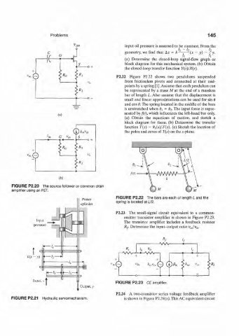
P2.22 Figure P2.22 shows two pendulums suspended
from frictionless pivots and connected at their mid-
points by a spring [1]. Assume that each pendulum can
be represented by a mass Mat the end of a massless
bar of length L. Also assume that the displacement is
small and linear approximations can be used for sin 8
and cos 8. The spring located in the middle of the bars
is unstretched when fy = 8 2. The input force is repre-
sented by /(r), which influences the left-hand bar only,
(a)
(a) Obtain the equations of motion, and sketch a
block diagram for them, (b) Determine the transfer
function T(s) = 8i(s)/F(s). (c) Sketch the location of
(P*"."* the poles and zeros of T(s) on the s-plane.
v
'in G gs
-> • •«
x
>*a > i
"it Q
0 2
n/WWW
(b)
FIGURE P2.20 The source follower or common drain
amplifier using an FET.
FIGURE P2.22 The bars are each of length L and the
Power
cylinder spring is located at L/2.
P2.23 The small-signal circuit equivalent to a common-
emitter transistor amplifier is shown in Figure P2.23.
Input The transistor amplifier includes a feedback resistor
pressure
Rf. Determine the input-output ratio v cJv- m.
->WSr
'c
r W V - o - * - ^ v V v — 1 -4 6 -
*(* - v)
*.© v bf ,,«,,© ®A
FIGURE P2.23 CE amplifier.
I Output, v
P2.24 A two-transistor series voltage feedback amplifier
FIGURE P2.21 Hydraulic servomechanism. is shown in Figure P2.24(a). This AC equivalent circuit