
Page 170 - Modern Control Systems
P. 170
144 Chapter 2 Mathematical Models of Systems
Obtain the relationship 7[ 3(s) between X^(s) and
X 3(s) by using Mason's signal-flow gain formula.
Compare the work necessary to obtain 7^0) by ma-
k, spring constant trix methods to that using Mason's signal-flow gain
formula.
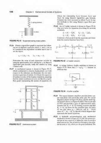
P2.18 An LC ladder network is shown in Figure P2.18.
One may write the equations describing the network
as follows:
h = (Vi ~ V u)Y h V a = (J, - / 0)Z 2,
I, = K - v 2)y 3, v 2 = / a z 4 .
Construct a flow graph from the equations and deter-
mine the transfer function K(s)/Vi(.r).
FIGURE P2.15 Suspended spring-mass system.
P2.16 Obtain a signal-flow graph to represent the follow- h L V L 0
J T Y Y V
ing set of algebraic equations where x\ and x 2 are to Y,
be considered the dependent variables and 6 and 11 1
are the inputs:
VAs)
Z 2
Xi + 1.5¾ = 6, 2JC, 4A-, 11.
Determine the value of each dependent variable by FIGURE P2.18 LC ladder network.
using the gain formula. After solving for JCJ by Mason's
signal-flow gain formula, verify the solution by using
Cramers rule. P2.19 A voltage follower (buffer amplifier) is shown in
Figure P2.19. Show that T = v Q/v in = 1. Assume an
P2.17 A mechanical system is shown in Figure P2.17, ideal op-amp.
which is subjected to a known displacement x$(t) with
respect to the reference, (a) Determine the two inde-
pendent equations of motion, (b) Obtain the equations
of motion in terms of the Laplace transform, assuming
that the initial conditions are zero, (c) Sketch a signal-
flow graph representing the system of equations, (d) + 0-
Friction
,r~ A/, * i FIGURE P2.19 A buffer amplifier.
f. P2.20 The source follower amplifier provides lower out-
,r" M 3 6, put impedance and essentially unity gain. The circuit
diagram is shown in Figure P2.20(a), and the small-sig-
i nal model is shown in Figure P2.20(b).This circuit uses
and
gain
FET
approximately
an
a
of
provides
unity.
r Assume that (a) R 2 Solve R] for biasing purposes and Solve
that
»
gain, (b)
amplifier
the
for
R 2.
Rg »
10 kil
=
2000 (t£l
=
and
R s
i
*4 i < J ZJ for the R s gain Ry when R 2. g m (c) Sketch a block diagram that
+
=
where
1 P2.21 represents the circuit equations. with mechanical
hydraulic
A
servomechanism
r feedback is shown in Figure P2.21 [18]. The power pis-
ton has an area equal to A. When the valve is moved a
small amount Az, the oil will flow through to the cylin-
FIGURE P2.17 Mechanical system. der at a rate p • Az, where p is the port coefficient. The