
Page 174 - Modern Control Systems
P. 174
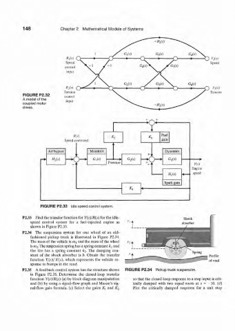
148              Chapter  2  Mathematical  Models of  Systems

                                                                      -H 2(s)


                              Speed                                                           Speed
                              control
                               input


                              R 2(S)  O                                                        r 2[s)
                             Tension                                                          Tension
           FIGURE  P2.32      control
           A model of the
                              input
           coupled motor
           drives.                                                    -HM


                   FIGURE  P2.33  Idle speed control system.

           P233  Find the transfer function  for  Y(s)/R(s)  for the idle-
               speed  control  system  for  a  fuel-injected  engine  as
               shown  in Figure P2.33.
           P2.34  The  suspension  system  for  one  wheel  of  an  old-
               fashioned  pickup  truck  is  illustrated  in  Figure  P2.34.
              The mass of the vehicle is m% and the mass of the wheel
               is m 2-The suspension spring has a spring constant k^ and
               the  tire  has  a  spring  constant  k 2.  The  damping  con-
              stant  of  the  shock  absorber  is b. Obtain  the  transfer
              function  Y\(s)j'X(s),  which  represents  the  vehicle  re-
              sponse to bumps in the road.
           P2.35  A feedback  control system has the structure shown   FIGURE P2.34  Pickup truck suspension.
              in  Figure  P2.35. Determine  the  closed-loop  transfer
              function  Y(s)/R(s)  (a) by block diagram  manipulation  so that the closed-loop response to a step input  is crit-
               and (b)  by using a signal-flow  graph  and Mason's sig-  ically  damped  with  two  equal  roots  at  s  = -10.  (d)
               nal-flow  gain  formula,  (c) Select  the  gains  /C, and  K 2  Plot  the  critically  damped  response  for  a  unit  step