
Page 179 - Modern Control Systems
P. 179
Advanced Problems 153
A D V A N C E D P R O B L E M S
AP2.1 An armature-controlled DC motor is driving a load.
The input voltage is 5 V. The speed at ( = 2 seconds is
30 rad/s, and the steady speed is 70 rad/s when t—*oo. I
Determine the transfer function <o(s)/V(s).
G dU)
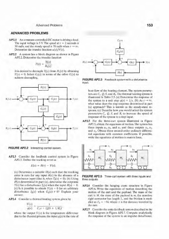
AP2.2 A system has a block diagram as shown in Figure
AP2.2. Determine the transfer function L
g(f) A'(.v) • G c(s) - » o - G(0
T(s) = *- n-o
It is desired to decouple Y(s) from R\(s) by obtaining H(s)
T(s) = 0. Select C 5 (J) in terms of the other Gj(s) to
achieve decoupling.
FIGURE AP2.3 Feedback system with a disturbance
input.
Hi(s)
heat flow of the heating element. The system parame-
The thermal heating system is
ters are C„ £?, S, and R r
G W illustrated in Table 2.5. (a) Determine the response of
R,(s) K_}~*" ' G,W • /,(.0 the system to a unit step q(s) = 1/s. (b) As t—*oo.
what value does the step response determined in part
(a) approach? This is known as the steady-state re-
C 5(.v)
sponse, (c) Describe how you would select the system
parameters C„ Q, 5, and R, to increase the speed of
J V
GeC) response of the system to a step input.
AP2.5 For the three-cart system illustrated in Figure
AP2.5, obtain the equations of motion.The system has
^o three inputs «j, 1¾. and u 3 and three outputs JC-,, JC 2 -
.,+
«-.(.0 • GiW • • K,(.0 and v 3. Obtain three second-order ordinary differen-
tial equations with constant coefficients. If possible,
write the equations of motion in matrix form.
sy*) 4
: >-.v.
FIGURE AP2.2 Interacting control system. l ". • *i • .V,
• ' - * •
AP2.3 Consider the feedback control system in Figure M, *3
AP2.3. Define the tracking error as . VvW- VvVA M 2 V\AAA M 3
E(t) = R(s) - Y(s).
h ( ) ( ) h O O h ( ) ( )
(a) Determine a suitable H(s) such that the tracking
error is zero for any input R(s) in the absence of a FIGURE AP2.5 Three-cart system with three inputs and
disturbance input (that is, when T lt(s) = 0). (b) Using three outputs.
H{s) determined in part (a), determine the response
Y(s) for a disturbance T,j(s) when the input R(s) = 0. AP2.6 Consider the hanging crane structure in Figure
(c) Is it possible to obtain Y(s) = 0 for an arbitrary AP2.6. Write the equations of motion describing the
disturbance T^(s) when G,i(s) ¥> 0? Explain your motion of the cart and the payload. The mass of the
answer. cart is M, the mass of the payload is m, the massless
AP2.4 Consider a thermal heating system given by rigid connector has length L, and the friction is mod-
eled as F t, = —b'x where x is the distance traveled by
g(') _ 1 the cart.
q(s) C,s + (QS + l/R.Y AP2.7 Consider the unity feedback system described in the
where the output 3"(.?) is the temperature difference block diagram in Figure AP2.7. Compute analytically
due to the thermal process, the input q(s) is the rate of the response of the system to an impulse disturbance.