
Page 183 - Modern Control Systems
P. 183
Computer Problems 157
JM COMPUTER PROBLEMS
CP2.1 Consider the two polynomials
/?(X = s .2 1 + 7s + 10
and Spring
Forcing
q(s) = s + 2. function <* constant
Compute the following .I'
(a) p(s)q(s) Mass Mass
(b) poles and zeros of G(s) = in displacement
Pis) y(?)
(C) /7(-1) Friction J,
CP2.2 Consider the feedback system depicted in Figure constant
CP2.2. b
(a) Compute the closed-loop transfer function using
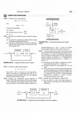
the series and feedback functions. FIGURE CP2.4 A mechanical spring-mass-damper
(b) Obtain the closed-loop system unit step response system.
with the step function, and verify that final value
of the output is 2/5.
unit step input. Let in = 10, k = 1, and b = 0.5. Show
that the peak amplitude of the output is about 1.8.
Controller Plant
CP2.5 A satellite single-axis attitude control system can
s + 2 be represented by the block diagram in Figure CP2.5.
A'f v i • The variables k, a, and b are controller parameters,
,v+ 1 j + 3 m
and J is the spacecraft moment of inertia. Suppose the
2
nominal moment of inertia is J = 10.8E8 (slug ft ),
and the controller parameters are k = 10.8E8, a = 1,
and 6 = 8.
FIGURE CP2.2 A negative feedback control system. (a) Develop an m-file script to compute the closed-
loop transfer function T(s) = 0(s)/0,i(s).
(b) Compute and plot the step response to a 10° step
CP2.3 Consider the differential equation input.
(c) The exact moment of inertia is generally unknown
y + 4y + 3y = u,
and may change slowly with time. Compare the
where y(0) = y(0) = 0 and u(t) is a unit step. Deter- step response performance of the spacecraft when
mine the solution y(t) analytically and verify by co- /is reduced by 20% and 50%. Use the controller
plotting the analytic solution and the step response parameters k = 10.8E8, a = 1, and b = 8 and a
obtained with the step function. 10° step input. Discuss your results.
CP2.4 Consider the mechanical system depicted in CP2.6 Consider the block diagram in Figure CP2.6.
Figure CP2.4.The input is given by/(i). and the output (a) Use an m-file to reduce the block diagram in
is y(t). Determine the transfer function from f(t) to Figure CP2.6, and compute the closed-loop trans-
y(t) and, using an m-file, plot the system response to a fer function.
Controller Spacecraft
0 dU) k(s + a) 1 0(1)
Desired • "> ,
s + b J* 2
attitude • altitude
FIGURE CP2.5 A spacecraft single-axis attitude control block diagram.