
Page 180 - Modern Control Systems
P. 180
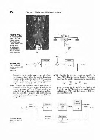
154              Chapter  2  Mathematical  Models  of  Systems


           FIGURE AP2.6
           (a) Hanging crane
           supporting the
           Space Shuttle
           Atlantis (Image
           Credit:  NASA/Jack
           Pfaller) and
           (b) schematic
           representation
           of the hanging
           crane structure.            (a)                           (b)

                                                           T d(s)
                                             Controller                Plant
                                       ,  EM               +
           FIGURE  AP2.7                        K           (  o         1
           Unity feedback                                  +           s + 20        •+•  Y(s)
           control system with
           controller
           G c(s)  -  K.

               Determine  a  relationship  between  the  gain  K  and  AP2.9  Consider  the  inverting  operational  amplifier  in
               the  minimum  time  it  takes  the  impulse  disturbance  Figure  AP2.9. Find  the  transfer  function  VJ,s){Vls),
               response  of  the  system  to  reach  y(r)  <  0.1. Assume   Show  that  the  transfer  function  can  be  expressed  as
               that K  >  0. For what value of K does the  disturbance
               response  first reach at y{t)  =  0.1 at r =  0.05?  G(s)     =  K, +  —  +  K&,
                                                                         V,(s)
           AP2.8  Consider  the  cable  reel  control  system  given  in
               Figure AP2.8. Find the value  of A  and  K such that the   where  the  gains  K P, K h  and  K D  are  functions  of
               percent  overshoot  is  P.O.  £  10%  and  a desired ve-  Cj, C 2, JRI,  and  R 2, This  circuit  is a proportional-inte-
               locity  of  50 m/s  in the  steady  state  is achieved.  Com-  gral-derivative  (PID)  controller  (more  on  PID  con-
               pute  the  closed-loop  response  v(f)  analytically  and  trollers in Chapter 7).
               confirm  that  the steady-state  response  and  P. O. meet
               the  specifications.

                                                                                Reel
                               Desired          Amplifier       Motor         dynamics   Actual cable
                            ,  velocity  +                       200   Torque    1      velocity
                       /?(,)= ^       K  • >  »   K                                            •  V{s)
                           -
                                       J     *                  s +  1          j  +  8


                                                Measured      Tachometer
           FIGURE  AP2.8                        velocity          1
           Cable reel control                                  0.25i  +  1
           system.