
Page 181 - Modern Control Systems
P. 181
Design Problems 155
c-,
Hf
R 2
l-WV
v,w<
-° K,M
FIGURE AP2.9 An inverting operational amplifier circuit
representing a PID controller.
DESIGN PROBLEMS
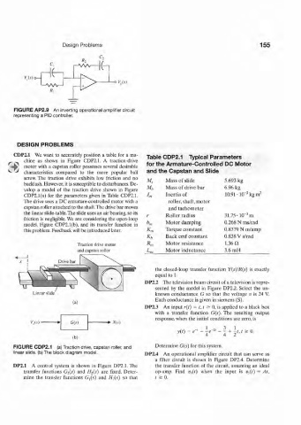
CDP2.1 We want to accurately position a table for a ma- Table CDP2.1 Typical Parameters
chine as shown in Figure CDP2.1. A traction-drive
motor with a capstan roller possesses several desirable for the Armature-Controlled DC Motor
characteristics compared to the more popular ball and the Capstan and Slide
screw. The traction drive exhibits low friction and no
M s Mass of slide 5.693 kg
backlash. However, it is susceptible to disturbances. De-
velop a model of the traction drive shown in Figure M,, Mass of drive bar 6.96 kg
3
CDP2.1(a) for the parameters given in Table CDP2.1. •'m Inertia of 10.91 • lfT kg m 2
The drive uses a DC armature-controlled motor with a roller, shaft, motor
capstan roller attached to the shaft.The drive bar moves and tachometer
the linear slide-table. The slide uses an air bearing, so its -
friction is negligible. We are considering the open-loop r Roller radius 31.75-10 ½
model, Figure CDP2.1(b), and its transfer function in b m Motor damping 0.268 N ms/rad
this problem. Feedback will be introduced later. Kn Torque constant 0.8379 N m/amp
K„ Back emf constant 0.838 Vs/rad
Traction drive motor Rm Motor resistance 1.36 Q,
and capstan roller L'm Motor inductance 3.6 mH
the closed-loop transfer function Y(s)!R($) is exactly
equal to 1.
DP2.2 The television beam circuit of a television is repre-
sented by the model in Figure DP2.2. Select the un-
Linear slide known conductance G so that the voltage v is 24 V.
Each conductance is given in Siemens (S).
(a)
DP2.3 An input r(t) = t, t a 0, is applied to a black box
with a transfer function G(s). The resulting output
response, when the initial conditions are zero, is
V„(-v) • G(s) X(s)
2
y(0 = - ' - ^ - ' - ^ + | / , / ^ 0 .
e
(b)
FIGURE CDP2.1 (a) Traction drive, capstan roller, and Determine G(s) for this system.
linear slide, (b) The block diagram model. DP2.4 An operational amplifier circuit that can serve as
a filter circuit is shown in Figure DP2.4. Determine
DP2.1 A control system is shown in Figure DP2.1. The the transfer function of the circuit, assuming an ideal
transfer functions G 2(s) and H 2(s) are fixed. Deter- op-amp. Find v t)(t) when the input is Uj(f) = At,
mine the transfer functions G {(s) and //](.?) so that t > 0 .