
Page 172 - Modern Control Systems
P. 172
146 Chapter 2 Mathematical Models of Systems
neglects the bias resistors and the shunt capacitors. A sign technique known as feedforward correction [19],
block diagram representing the circuit is shown in Recent experiments have shown that this technique
Figure P2.24(b).This block diagram neglects the effect offers the potential for yielding excellent amplifier
of h n., which is usually an accurate approximation, and stabilization. Black's amplifier is shown in Figure
assumes that R 2 + RL » R\- (a) Determine the volt- P2.25(a) in the form recorded in 1924. The block dia-
age gain vjv in. (b) Determine the current gain ia/lbi- gram is shown in Figure P2.25(b). Determine the
(c) Determine the input impedance V\Jib\. transfer function between the output Y(s) and the
input R(s) and between the output and the distur-
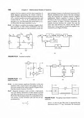
P2.25 H. S. Black is noted for developing a negative feed-
back amplifier in 1927. Often overlooked is the fact bance T d(s). G(s) is used to denote the amplifier rep-
resented by fi
in Figure P2.25(a).
that three years earlier he had invented a circuit de-
'ft i R
+ R,
M "ir
(a; (bl
FIGURE P2.24 Feedback amplifier.
A'(v) • ns)
1 G(s)
G(s)
H^\P- J J .
FIGURE P2.25 H S
Black's amplifier. (a) (h)
P2.26 A robot includes significant flexibility in the arm
members with a heavy load in the gripper [6, 20]. A
two-mass model of the robot is shown in Figure. P2.26.
Find the transfer function Y(s)IF(s).
P2.27 Magnetic levitation trains provide a high-speed, Pit)'
very low friction alternative to steel wheels on steel
rails. The train floats on an air gap as shown in Figure VWWVWA
P2.27 [25]. The levitation force F L is controlled by the k
coil current i in the levitation coils and may be ap- FIGURE P2.26 The spring-mass-damper model of a
proximated by robot arm.
where z is the air gap. This force is opposed by the
V downward force F = mg. Determine the linearized