
Page 162 - Modern Control Systems
P. 162
136 Chapter 2 Mathematical Models of Systems
«2 +
^ W v - R(s) r~\ Gito — • G 2 W Hs)
_ . i
+ 0-
WW
TT
(a)
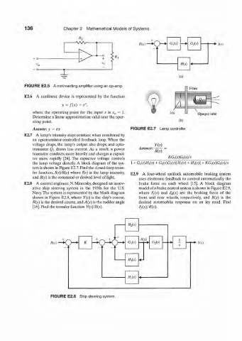
FIGURE E2.5 A noninverting amplifier using an op-amp.
Filter
E2.6 A nonlinear device is represented by the function
A N
y = /{X) = *,
e
\
where the operating point for the input x is x 0 = 1. Iris Opaque tube
Determine a linear approximation valid near the oper-
ating point. fb)
Answer: y = ex FIGURE E2.7 Lamp controller.
E2.7 A lamp's intensity stays constant when monitored by
an optotransistor-controlled feedback loop. When the
voltage drops, the lamp's output also drops, and opto-
transistor Q\ draws less current. As a result, a power Answer: R( S)
transistor conducts more heavily and charges a capaci-
tor more rapidly [24]. The capacitor voltage controls KG,(*)G 2(s)/j
the lamp voltage directly. A block diagram of the sys- 1 + G 1(s)H ?,(s) + <h(*yGffMiW + //*(*)] + KCh(s)GAs)/s
tem is shown in Figure E2.7. Find the closed-loop trans-
fer function, I(s)!R(s) where I{s) is the lamp intensity,
E2.9 A four-wheel antilock automobile braking system
and R(s) is the command or desired level of light.
uses electronic feedback to control automatically the
E2.8 A control engineer, N. Minorsky, designed an innov- brake force on each wheel [15]. A block diagram
ative ship steering system in the 1930s for the U.S. model of a brake control system is shown in Figure E2.9,
Navy. The system is represented by the block diagram where iy(s) and F R(s) are the braking force of the
shown in Figure E2.8, where Y(s) is the ship's course, front and rear wheels, respectively, and R{s) is the
/?(.?) is the desired course, and A(s) is the rudder angle desired automobile response on an icy road. Find
[16]. Find the transfer function Y(s)IR(s). F f(s)/R(s).
H 2{s)
R(s)• ky4 G?iW A G 2(s) -*• I Y(s)
s
ffjW «-
//,(•')
FIGURE E2.8 Ship steering system.