
Page 161 - Modern Control Systems
P. 161
Exercises 135
h. Laplace transform Unidirectional, operational blocks that represent the
transfer functions of the elements of the system.
i. Linear A rule that enables the user to obtain a transfer
approximation function by tracing paths and loops within a system.
j . Linear system An electric actuator that uses an input voltage as
a control variable.
k. Mason loop rule The ratio of the Laplace transform of the output
variable to the Laplace transform of the input variable.
1. Mathematical Descriptions of the behavior of a system using
models mathematics.
A model of a system that is used to investigate the
m. Signal-flow graph behavior of a system by utilizing actual input signals.
A diagram that consists of nodes connected by several
n. Simulation directed branches and that is a graphical representation
of a set of linear relations.
o. Transfer function An approximate model that results in a linear relationship
between the output and the input of the device.
EXERCISES
Exercises are straightforward applications of the concepts
of the chapter.
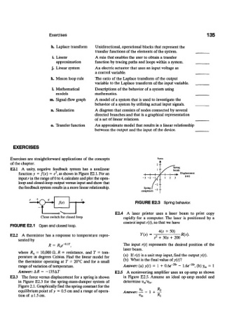
E2.1 A unity, negative feedback system has a nonlinear Spring
breaks
2
function y = /(e) = e , as shown in Figure E2.1. For an H—I—h I fc Displacement
input r in the range of 0 to 4, calculate and plot the open- "™' (em)
loop and closed-loop output versus input and show that
the feedback system results in a more linear relationship. Springf
compresses
FIGURE E2.3 Spring behavior.
E2.4 A laser printer uses a laser beam to print copy
Close switch for closed loop rapidly for a computer. The laser is positioned by a
control input r(t), so that we have
FIGURE E2.1 Open and closed loop.
4(s + 50)
E2.2 A thermistor has a response to temperature repre- 7 ( 5 ) - s 2 + 30s + 200 R(s).
sented by
= /^-01-^ The input r(t) represents the desired position of the
R
laser beam.
where R 0 = 10,000 ft, R = resistance, and T = tem-
perature in degrees Celsius. Find the linear model for (a) If r(t) is a unit step input, find the output y(t).
the thermistor operating at T = 20°C and for a small (b) What is the final value of y{t)l
10
20
range of variation of temperature. Answer: (a) y{t) = 1 + 0.6<T ' - 1.6<T ', (b) y ss = 1
Answer: AR = -135AF E2.5 A noninverting amplifier uses an op-amp as shown
E2.3 The force versus displacement for a spring is shown in Figure E2.5. Assume an ideal op-amp model and
in Figure E2.3 for the spring-mass-damper system of determine v 0/v m.
Figure 2.1. Graphically find the spring constant for the
equilibrium point of y = 0.5 cm and a range of opera-
Answer: — - 1 + —
tion of ±1.5 cm.