
Page 163 - Modern Control Systems
P. 163
Exercises 137
H 2(s)
G 2(.t) *• FAx) Plunger
R(s\ • G,(s)
G 3(s) *• Fsis)
H 2(s)
FIGURE E2.9 Brake control system.
Damping
orifice
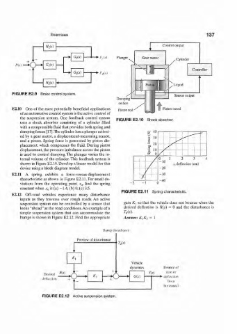
E2.10 One of the most potentially beneficial applications Piston rod Piston travel
of an automotive control system is the active control of
the suspension system. One feedback control system FIGURE E2.10 Shock absorber.
uses a shock absorber consisting of a cylinder filled
with a compressible fluid that provides both spring and
damping forces [17].The cylinder has a plunger activat-
ed by a gear motor, a displacement-measuring sensor,
and a piston. Spring force is generated by piston dis-
placement, which compresses the fluid. During piston
displacement, the pressure unbalance across the piston
is used to control damping. The plunger varies the in-
ternal volume of the cylinder. This feedback system is
shown in Figure E2.10. Develop a linear model for this
device using a block diagram model.
E2.ll A spring exhibits a force-versus-displacement
characteristic as shown in Figure E2.ll. For small de-
viations from the operating point x 0, find the spring
constant when x 0 is (a) -1.4; (b) 0; (c) 3.5.
FIGURE E2.11 Spring characteristic.
E2.12 Off-road vehicles experience many disturbance
inputs as they traverse over rough roads. An active
suspension system can be controlled by a sensor that gain K x so that the vehicle does not bounce when the
looks "ahead" at the road conditions. An example of a desired deflection is R{s) = 0 and the disturbance is
simple suspension system that can accommodate the Us).
bumps is shown in Figure E2.12. Find the appropriate Answer: K^K^ = 1
Bump disturbance
Preview of disturbance
1 'j( r;
< •
* i
dynamics Bounce of
Js + .. m auto or
Desired «»>
K 2 G(.v)
deflection + S J T<~>
. _ horizontal
FIGURE E2.12 Active suspension system.