
Page 261 - Modern Control Systems
P. 261
Section 4.1 Introduction 235
4.1 INTRODUCTION
A control system is defined as an interconnection of components forming a system
that will provide a desired system response. Because the desired system response
is known, a signal proportional to the error between the desired and the actual
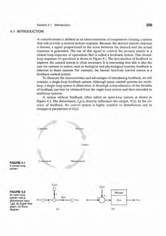
response is generated. The use of this signal to control the process results in a
closed-loop sequence of operations that is called a feedback system. This closed-
loop sequence of operations is shown in Figure 4.1. The introduction of feedback to
improve the control system is often necessary. It is interesting that this is also the
case for systems in nature, such as biological and physiological systems; feedback is
inherent in these systems. For example, the human heartrate control system is a
feedback control system.
To illustrate the characteristics and advantages of introducing feedback, we will
consider a single-loop feedback system. Although many control systems are multi-
loop, a single-loop system is illustrative. A thorough comprehension of the benefits
of feedback can best be obtained from the single-loop system and then extended to
multiloop systems.
A system without feedback, often called an open-loop system, is shown in
Figure 4.2. The disturbance, T d(s), directly influences the output, Y(s). In the ab-
sence of feedback, the control system is highly sensitive to disturbances and to
changes in parameters of G(s).
Controller Process
Output
Comparison Measurement
FIGURE 4.1
A closed-loop
system.
W
FIGURE 4.2 Process
An open-loop
system with a G(s)
disturbance input, R(s - * - — O ns) R(s) C(.v) + ns)
T d(s). (a) Signal-flow
graph, (b) Block
diagram. (b)