
Page 257 - Modern Control Systems
P. 257
Computer Problems 231
DP3.5 Consider the single-input, single-output system de- u(t) = -Kx(r) + r(/),
scribed by
where r(t) is the reference input. Determine K =
x(0 = Ax(0 + Bu(t) [K\ K 2\ so that the closed-loop system
y(t) = Cx(0
x(/) = [A - BK]x(/) + Br(t)
where
~ 0 r "o y(t) = Cx(0
A = 3 ,B = , C = [1 0].
|_-2 J [ij possesses closed-loop eigenvalues at /j and r 2. Note that
if /*! = cr 4- jw is a complex number, then r 2 = a — jw
Assume that the input is a linear combination of the is its complex conjugate.
states, that is,
COMPUTER PROBLEMS
CP3.1 Determine a state variable representation for the
following transfer functions (without feedback) using
the SS function:
1
(a) G{s) =
s + 10
s 2 + 5s + 3
(b) G(s) =
s 2 + 8s + 5 V ()(.v)
5 + 1
(c) G(s)
7,
s + 3s 2 + 3s + 1
CP3.2 Determine a transfer function representation for the
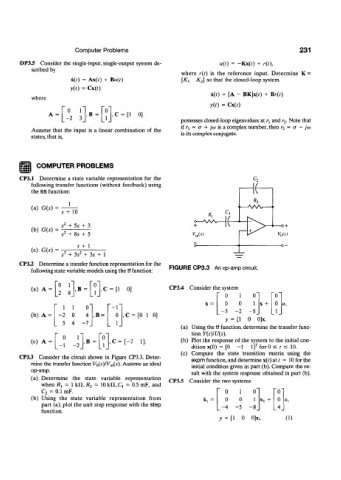
following state variable models using the tf function: FIGURE CP3.3 An op-amp circuit.
0 r V
(a) A = 2 8 ,B = C = [l 0] CP3.4 Consider the system
L J [lj 0 1 o" "o"
1 1 o" " - 1 " 0 0 1 x + 0 H,
(b) A = 2 0 4 ,B = 0 , C = [0 1 0] - 3 -2 5_ _1_
y = [1 0 0]x.
5 4 -7_ 1_
(a) Using the tf function, determine the transfer func-
0 r "o tion Y(s)/U(s).
(c) A = ,B = i ,C = [-2 1]. (b) Plot the response of the system to the initial con-
[-1 -2 J LJ dition x(0) = [0 - 1 i f for 0 ^ t < 10.
(c) Compute the state transition matrix using the
CP33 Consider the circuit shown in Figure CP3.3. Deter- expm function,and determine x(r) at/ = 10 for the
mine the transfer function Vo(s)/V m(s). Assume an ideal initial condition given in part (b). Compare the re-
op-amp.
sult with the system response obtained in part (b).
(a) Determine the state variable representation CP3.5 Consider the two systems
when 7?i = 1 kXl, R 2 = 10 kfl, C, = 0.5 mF, and
C 2 = 0.1 mF. 0 1 o" ~o"
(b) Using the state variable representation from Xl 0 0 1 x t + 0
part (a), plot the unit step response with the step 4 - 5 -8_ _4_
function.
y = [l 0 0] Xl 0)