
Page 254 - Modern Control Systems
P. 254
228 Chapter 3 State Variable Models
AP3.4 Front suspensions have become standard equip-
ment on mountain bikes. Replacing the rigid fork that
attaches the bicycle's front tire to its frame, such sus-
pensions absorb bump impact energy, shielding both
frame and rider from jolts. Commonly used forks,
however, use only one spring constant and treat bump
impacts at high and low speeds—impacts that vary
greatly in severity—essentially the same.
A suspension system with multiple settings that are
adjustable while the bike is in motion would be attrac-
tive. One air and coil spring with an oil damper is
available that permits an adjustment of the damping
constant to the terrain as well as to the rider's weight
[17]. The suspension system model is shown in Figure
AP3.4, where b is adjustable. Select the appropriate
value for b so that the bike accommodates (a) a large
Gap sensor bump at high speeds and (b) a small bump at low
speeds. Assume that k%= \ and ki = 2.
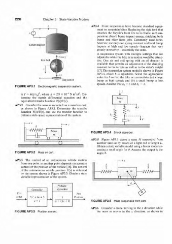
FIGURE AP3.1 Electromagnetic suspension system.
f
2
4
2
is / = k(i tlx g) , where k = 2.9 x ItT N nr/A . De-
termine the matrix differential equation and the Mass
equivalent transfer function X(s)IV(s). m
AP3.2 Consider the mass m mounted on a massless cart,
as shown in Figure AP3.2. Determine the transfer Iv
function Y(s)/U(s), and use the transfer function to
obtain a state-space representation of the system. * 2
£
>
Mass
FIGURE AP3.4 Shock absorber.
IT JJ AP3.5 Figure AP3.5 shows a mass A/ suspended from
u u another mass m by means of a light rod of length L.
Obtain a state variable model using a linear model as-
suming a small angle for 9. Assume the output is the
FIGURE AP3.2 Mass on cart. angle, 6.
AP3.3 The control of an autonomous vehicle motion
from one point to another point depends on accurate
control of the position of the vehicle [16]. The control
of the autonomous vehicle position Y(s) is obtained
by the system shown hi Figure AP3.3. Obtain a state
variable representation of the system.
Vehicle
Controller dynamics
K(.v)
Input 2i- + 6.v + 5 1 Position
2
s • 1 (s+ l)(.s+ 2) FIGURE AP3.5 Mass suspended from cart.
AP3.6 Consider a crane moving in the x direction while
FIGURE AP3.3 Position control. the mass m moves in the z direction, as shown in