
Page 251 - Modern Control Systems
P. 251
Problems 225
where x-, = temperature deviation from desired equi-
librium, and x 2 = temperature of the storage material
(such as a water tank). Also, u\ and u 2 are the respec-
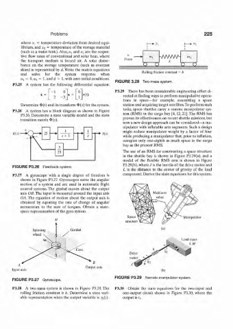
tive flow rates of conventional and solar heat, where 1{ '» 1 vwvw- « 7
Force
the transport medium is forced air. A solar distur- k
bance on the storage temperature (such as overcast O O 0 0
skies) is represented by d. Write the matrix equations
and solve for the system response when Rolling friction constant = b
«i = 0, H 2 = l,andrf = 1, with zero initial conditions.
FIGURE 3.28 Two-mass system.
P3.25 A system has the following differential equation:
P3.29 There has been considerable engineering effort di-
x + r{t). rected at finding ways to perform manipulative opera-
tions in space—for example, assembling a space
Determine 4>(r) and its transform ¢(^) for the system. station and acquiring target satellites. To perform such
tasks, space shuttles carry a remote manipulator sys-
P3.26 A system has a block diagram as shown in Figure
P3.26. Determine a state variable model and the state tem (RMS) in the cargo bay [4,12,21]. The RMS has
transition matrix ¢(5). proven its effectiveness on recent shuttle missions, but
now a new design approach can be considered—a ma-
nipulator with inflatable arm segments. Such a design
1 1 might reduce manipulator weight by a factor of four
R(s) 25 Y(s)
s + 3 s while producing a manipulator that, prior to inflation,
occupies only one-eighth as much space in the cargo
bay as the present RMS.
3
25 The use of an RMS for constructing a space structure
in the shuttle bay is shown in Figure P3.29(a), and a
model of the flexible RMS arm is shown in Figure
P3.29(b), where J is the inertia of the drive motor and
FIGURE P3.26 Feedback system.
L is the distance to the center of gravity of the load
P3.27 A gyroscope with a single degree of freedom is component. Derive the state equations for this system.
shown in Figure P3.27. Gyroscopes sense the angular
motion of a system and are used in automatic flight
control systems. The gimbal moves about the output
axis OB. The input is measured around the input axis
OA. The equation of motion about the output axis is
obtained by equating the rate of change of angular
momentum to the sum of torques. Obtain a state-
space representation of the gyro system.
Space Manipulator
structure
Spinning Gimbal (a)
wheel
Load mass
I, M
B
Output axis
FIGURE P3.29 Remote manipulator system.
FIGURE P3.27 Gyroscope.
P3.28 A two-mass system is shown in Figure P3.28. The P3.30 Obtain the state equations for the two-input and
rolling friction constant is /;. Determine a state vari- one-output circuit shown in Figure P3.30, where the
able representation when the output variable is yi(t). output is i%.