
Page 247 - Modern Control Systems
P. 247
Problems 221
Controller
Voltage Velocity
1
Hs)
-N
RU) — K 3 > s+ l . 9 - 2 1 Position
s + 6
I
FIGURE P3.5
Closed-loop
system.
Actuator
R[s) m
+ /~N 1 Depth
Desired K S G(s) - s
depth
Pressure
measurement
i i ^ ,
FIGURE P3.6 RLC circuit. FIGURE P3.7 Submarine depth control.
by a pressure transducer. The gain of the stern plane
actuator is K = 1 when the vertical velocity is 25 m/s. Module
The submarine has the transfer function
r•<^ {s + 1 ) 2
Cis) =
7TT
and the feedback transducer is H(s) = 2s + 1. Deter-
mine a state variable representation for the system.
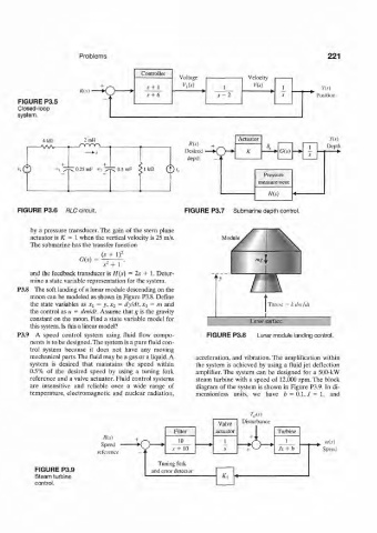
P3.8 The soft landing of a lunar module descending on the
moon can be modeled as shown in Figure P3.8. Define
the state variables as Xi = y, JC 2 = dyldt, x 3 = m and
the control as u = dmldt. Assume that g is the gravity
constant on the moon. Find a state variable model for Lunar surface
this system. Is this a linear model?
P3.9 A speed control system using fluid flow compo- FIGURE P3.8 Lunar module landing control.
nents is to be designed. The system is a pure fluid con-
trol system because it does not have any moving
mechanical parts. The fluid may be a gas or a liquid. A acceleration, and vibration. The amplification within
system is desired that maintains the speed within the system is achieved by using a fluid jet deflection
0.5% of the desired speed by using a tuning fork amplifier. The system can be designed for a 500-kW
reference and a valve actuator. Fluid control systems steam turbine with a speed of 12,000 rpm. The block
are insensitive and reliable over a wide range of diagram of the system is shown in Figure P3.9. In di-
temperature, electromagnetic and nuclear radiation, mensionless units, we have ¢ = 0.1,/ = 1, and
7-,,(.0
Valve Disturbance
Filter actuator Turbine
Ris) s 4-
"> fc 10 1 1 ^ (0(X)
Speed •
5 + 1 0 Js + b Speed
reference
Tu ning fork
FIGURE P3.9 and error detector
Steam turbine - A.] •«
control.