Page 246 - Modern Control Systems
P. 246

220              Chapter 3  State Variable Models
                Obtain  the  transfer  function  G(s)  =  Y(s)/U(s)  and    x  = ax  +  bu
                determine  the  response  of  the  system  to  a  unit  step  y  —  cx  +  du
                input.
                                                             where  a, b, c, and  d  are  scalars  such  that  the  transfer
            E3.22  Consider the system in state variable  form
                                                             function  is the same  as obtained in (a).
                              x  =  Ax  +  Bit            E3.23  Consider a system modeled via the third-order  dif-
                              y  = Cx  +  Du                 ferential  equation
                with                                                 'x\t)  +  3x(0  +  3x(0  +  x{t)
                    "3  2'    " 1 '
                A  =     ,B  =    , C  =  [1  0], and D  =  [0].         =  u(t)  + 2ii(t)  +  4ii(t)  +  (t).
                    b  4J     L-iJ
                                                             Develop  a state variable representation  and  obtain  a
            (a)  Compute  the  transfer  function  G(s)  =  Y(s)/U(s).  block  diagram  of  the  system  assuming  the  output  is
                (b) Determine  the poles and zeros of the system, (c) If   x(t)  and  the input  is  u(t).
                possible, represent  the  system  as  a first-order  system


             PROBLEMS

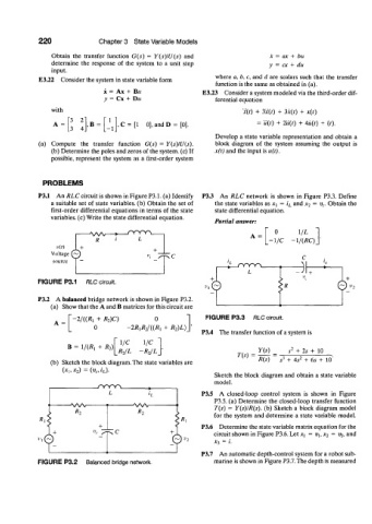
            P3.1  An RLC  circuit is shown in Figure P3.1. (a)  Identify  P33  An  RLC  network  is  shown  in  Figure  P3.3.  Define
                a suitable  set  of state variables, (b)  Obtain  the  set  of  the state variables as x^  =  i L  and x 2  =  v c. Obtain  the
                first-order  differential  equations  in terms  of  the state   state differential  equation.
               variables, (c) Write the state differential  equation.
                                                             Partial  answer:
                                                                              0      \/L
                          -A/W-                                        A  =
                                        L                                    •1/C   -l/(RC)
                            R
                 v(t)   +
                Voltage  ^ y
                source
                                                                      L            ~j[
            FIGURE P3.1  RLC circuit.
                                                                                               ©
            P3.2  A balanced bridge network  is shown in Figure P3.2.
               (a)  Show that the A and B matrices for this circuit are
                      - 2 / ( ( ^  +  R 2)C)  0           FIGURE P3.3   RLC circuit.
                           0         -2R lR 2/((R l  +  R 2)L)_
                                                         P3.4  The transfer  function  of a system is
                                   1/C   1/C
                    B  =  1/(/^  +  R 2)                                          2
                                 IR 2/L  -R2JL]                          Y(s)    s  + 2s  +  10
                                                                   T(s)              2
               (b)  Sketch the block diagram. The state variables  are   R(s)  ~  s* + 4s  + 6s  +  10'
                   (x h  x 2) =  (v c,  i L).
                                                             Sketch  the  block  diagram  and  obtain  a state  variable
                                                             model.
                                                         P3.5  A  closed-loop  control  system  is  shown  in  Figure
                                                             P3.5. (a) Determine  the closed-loop transfer  function
                                                             T(s)  =  Y(s)IR(s).  (b)  Sketch  a block  diagram  model
                                                             for  the  system  and determine  a state variable  model.
                                                         P3.6  Determine the state variable matrix equation  for the
                                                             circuit shown in Figure P3.6. Let  Xj  = V\, x 2  = V2, and
                                                             JC3  =  i.
                                                         P3.7  An automatic depth-control system for a robot sub-
            FIGURE P3.2  Balanced bridge network.            marine is shown in Figure P3.7.The depth is measured
   241   242   243   244   245   246   247   248   249   250   251