
Page 242 - Modern Control Systems
P. 242
216 Chapter 3 State Variable Models
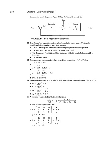
Consider the block diagram in Figure 3.43 for Problems 12 through 14:
Controller Process
+ ^ E a{s) 10
RU) •O o s+ 10 +>Y{s)
FIGURE 3.43 Block diagram for the Skills Check.
12. The effect of the input R(s) and the disturbance T d(s) on the output Y(s) can be
considered independently of each other because:
a. This is a linear system, therefore we can apply the principle of superposition.
b. The input R(s) does not influence the disturbance T d(s).
c. The disturbance T d(s) occurs at high frequency, while the input R(s) occurs at low
frequency.
d. The system is causal.
13. The state-space representation of the closed-loop system from R(s) to Y(s) is:
x = -10* + lOKr
a.
y = x
x = -(10 + lOK)x + r
b.
y = 10*
.1-=-(10+ IOJQJC + lOKr
c
v = x
d. None of the above
14. The steady-state error E{s) = Y{s) - R(s) due to a unit step disturbance T (t(s) = l/.v is:
a. e ss = lim e(t) = oo
f->0O
b. e ss = Iime(/) = 1
1
c. e^ = lime(r) =
/-»00 K + 1
d. e ss = lim e(t) = K + I
/—»oo
15. A system is represented by the transfer function + 10)
5(5
= T(s) =
2
R{s) 5 3 + 10s + 205 + 50'
A state variable representation is:
-10 -20 50" ~r
1 0 0 x + i
0 1 0 _ _0_
y = [0 5 50]x
"-10 -20 50" " l "
b. x = 1 0 0 x + 0
0 1 0 _ _0_
y = [l 0 50]x