
Page 237 - Modern Control Systems
P. 237
Section 3.10 Sequential Design Example: Disk Drive Read System 211
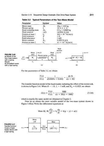
Table 3.2 Typical Parameters of the Two-Mass Model
Parameter Symbol Value
Motor mass M x 20 g = 0.02 kg
Flexure spring k 10 ^ k < oo
Head mounting mass Mi 0.5 g = 0.0005 kg
Head position x 2(t) variable in mm
3
Friction at mass 1 bi 410 x 10" N/(m/s)
Field resistance R in
Field inductance L lmH
Motor constant K,n 0.1025 Nm/A
_3
Friction at mass 2 b 2 4.1 x 10 N/(m/s)
Head
position
Motor —•</(/) Head —*.v(r) i—• v(t)
FIGURE 3.40 mass Flexure spring mass i
(a) Model of the «(0
two-mass system Force > M x -M/vW- M 2 u(t) • M = M x + M 2
with a spring k
flexure. b,
(b) Simplified model
with a rigid spring. (a) (b)
For the parameters of Table 3.2, we obtain
Y(s) 1 48.78
U(s) s(0.0205s + 0.410) s(s + 20)'
The transfer function model of the head reader, including the effect of the motor coil,
is shown in Figure 3.41. When R = 1 Cl, L = 1 mH, and K m = 0.1025, we obtain
Y(s) = 5000
G(s) = (3.118)
V(s) s(s + 20)(s + 1000)'
which is exactly the same model we obtained in Chapter 2.
Now let us obtain the state variable model of the two-mass system shown in
Figure 3.40(a). Write the differential equations as
2
d q da
Mass M x: Mi—7 + /7,-^- + k(q - y) = u(t)
2
dt dt v* "
Motor
coil Mass
FIGURE 3.41
Transfer function K m U(s) I
model of head V(.v) Ls + R s(Ms + b t) m)
reader device with Force
a rigid spring.