
Page 250 - Modern Control Systems
P. 250
2 2 4 Chapter 3 State Variable Models
X, I 7 1
1 X = Xenon 135
\ I
1 I = Iodine 135
? ;
I
v X
§ A 1 6
\io
I 2
\
1 \
10 15
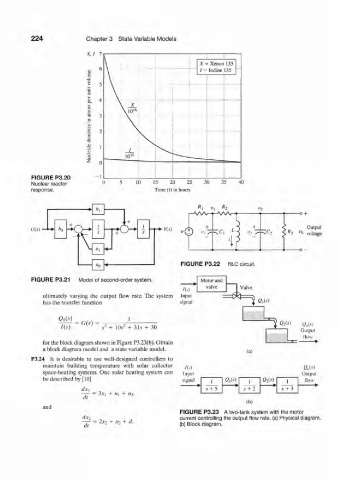
FIGURE P3.20 1
Nuclear reactor 10 15 20 25 30 35 40
response. Time (t) in hours
-o +
K Oulput
V(s) • fc — 4 -K % s Y(s) ;Cj < R 3 ^o voltage
J
\
V «1
FIGURE P3.22 RLC circuit.
«0
FIGURE P3.21 Model of second-order system. Motor and
valve 1 Valve
/(.0
ultimately varying the output flow rate. The system Input
has the transfer function signal | Q,(s)
1 ^ ¾
3
= G(.v) I & M <2 0 (.v)
S 3 + 10J 2 + 31s + 30
Output
flow
for the block diagram shown in Figure P3.23(b). Obtain
a block diagram model and a state variable model.
(a)
P3.24 It is desirable to use well-designed controllers to
maintain building temperature with solar collector
/CO Q„U)
space-heating systems. One solar heating system can Input Output
i n p Ut
be described by [10] signal 1 am i Qii-i) 1 flow
s + 5 s + 2 s + 3
= 3.V) + Hi + U%
(it
lb)
and
FIGURE P3.23 A two-tank system with the motor
dx 2 current controlling the output flow rate, (a) Physical diagram.
2*2 + «2 + d,
dt (b) Block diagram.