
Page 253 - Modern Control Systems
P. 253
Advanced Problems 227
motor friction is negligible. The motor and valve iner- : 1
2
tia is J = 0.006, and the area of the tank is 50 m . L _/-,,'. .^;';..i.i.jy
Note that the motor is controlled by the armature cur- * i i
rent i„. Let X\ = h, x 2 = 6, and x 3 = dd/dt. Assume
that q x = 800, where 6 is the shaft angle. The output
flow is qo - 50h(t).
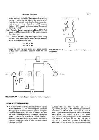
P3.36 Consider the two-mass system in Figure P3.36. Find T k 2
a state variable representation of the system. Assume
the output is x. 4 1
P3.37 Consider the block diagram in Figure P3.37. Using
the block diagram as a guide, obtain the state variable T ^
model of the system in the form M 2
T
x = Ax + Bu
y = Cx + DH
nit)
Using the state variable model as a guide, obtain FIGURE P3.36 Two-mass system with two springs and
a third-order differential equation model for the
system. one damper.
U(s)
FIGURE P3.37 A block diagram model of a third-order system.
ADVANCED PROBLEMS
AP3.1 Consider the electromagnetic suspension system Assume that the state variables are JCJ = x,
shown in Figure AP3.1. An electromagnet is located at x 2 = dxldt, and .r 3 = i. The electromagnet has an in-
the upper part of the experimental system. Using the ductance L = 0.508 H and a resistance R = 23.2 il.
electromagnetic force /, we want to suspend the iron Use a Taylor series approximation for the electromag-
ball. Note that this simple electromagnetic suspension netic force. The current is i± = / 0 + i, where
system is essentially unworkable. Hence feedback / 0 = 1.06 A is the operating point and i is the variable.
control is indispensable. As a gap sensor, a standard The mass m is equal to 1.75 kg. The gap is
induction probe of the type of eddy current is placed x g = X Q + x, where XQ = 4.36 mm is the operating
below the ball [20]. point and x is the variable. The electromagnetic force