
Page 255 - Modern Control Systems
P. 255
Advanced Problems 229
>• x
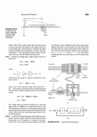
FIGURE AP3.6
A crane moving
in the x-direction
while the mass
moves in the
z-direction.
Figure AP3.6. The trolley motor and the hoist motor (a) Obtain a state variable model of the closed-loop
are very powerful with respect to the mass of the trol- system with input r(t) and output y(t). (b) Determine
ley, the hoist wire, and the load m. Consider the input the characteristic roots of the system and compute K
control variables as the distances D and R. Also as- such that the characteristic values are all co-located
sume that 8 < 50°. Determine a linear model, and de- at Si = - 2 , ¾ = -2, and S3 = 2 . (c) Determine
-
scribe the state variable differential equation. analytically the unit step-response of the closed-loop
AP3.7 Consider the single-input, single-output system de- system.
scribed by
x(r) = Ax(0 + B«(r)
y(t) = Cx(r) Top View
where
,B = C = [ 2 1].
Assume that the input is a linear combination of the
states, that is,
u{t) = -Kx(0 + r(t),
where r(t) is the reference input. The matrix K =
[AT] K 2] is known as the gain matrix. Substituting u(t)
into the state variable equation gives the closed-loop
system
Platen Linear motor
x(r) = [A - BK]x(0 + B/-(r)
Side View Motor
y(t) = cx(?) with lead screw
(a)
The design process involves finding K so that the
eigenvalues of A-BK are at desired locations in the
Y(s)
left-half plane. Compute the characteristic polynomial .v-position
associated with the closed-loop system and determine R(s) ~\ » K — • 1
2
values of K so that the closed-loop eigenvalues are in f s(s + 6s+ 12)
the left-half plane.
AP3.8 A system for dispensing radioactive fluid into cap-
sules is shown in Figure AP3.8(a).The horkontal axis (b)
moving the tray of capsules is actuated by a linear
motor. The .v-axis control is shown in Figure AP3.8(b). FIGURE AP3.8 Automatic fluid dispenser.