
Page 68 - Modern Control Systems
P. 68
Chapter 1 Introduction to Control Systems
emissions significantly. Sketch a block diagram for P1.19 Ichiro Masaki of General Motors has patented a
such a system for an automobile. system that automatically adjusts a car's speed to keep
16 All humans have experienced a fever associated a safe distance from vehicles in front. Using a video
with an illness. A fever is related to the changing of the camera, the system detects and stores a reference
control input in the body's thermostat. This thermo- image of the car in front. It then compares this image
stat, within the brain, normally regulates temperature with a stream of incoming live images as the two cars
near 98°F in spite of external temperatures ranging move down the highway and calculates the distance.
from 0° to 100°F or more. For a fever, the input, or de- Masaki suggests that the system could control steering
sired, temperature is increased. Even to many scien- as well as speed, allowing drivers to lock on to the car
tists, it often comes as a surprise to learn that fever ahead and get a "computerized tow." Sketch a block
does not indicate something wrong with body temper- diagram for the control system.
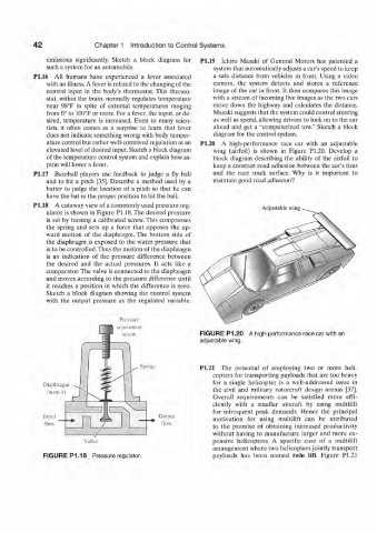
ature control but rather well-contrived regulation at an P1.20 A high-performance race car with an adjustable
elevated level of desired input. Sketch a block diagram wing (airfoil) is shown in Figure PI.20. Develop a
of the temperature control system and explain how as- block diagram describing the ability of the airfoil to
pirin will lower a fever. keep a constant road adhesion between the car's tires
17 Baseball players use feedback to judge a fly ball and the race track surface. Why is it important to
and to hit a pitch [35]. Describe a method used by a maintain good road adhesion?
batter to judge the location of a pitch so that he can
have the bat in the proper position to hit the ball.
18 A cutaway view of a commonly used pressure reg- Adjustable wing
ulator is shown in Figure PI. 18.The desired pressure
is set by turning a calibrated screw. This compresses
the spring and sets up a force that opposes the up-
ward motion of the diaphragm. The bottom side of
the diaphragm is exposed to the water pressure that
is to be controlled/Thus the motion of the diaphragm
is an indication of the pressure difference between
the desired and the actual pressures. It acts like a
comparator. The valve is connected to the diaphragm
and moves according to the pressure difference until
it reaches a position in which the difference is zero.
Sketch a block diagram showing the control system
with the output pressure as the regulated variable.
FIGURE P1.20 A high-performance race car with an
adjustable wing.
Spring P1.21 The potential of employing two or more heli-
copters for transporting payloads that are too heavy
for a single helicopter is a well-addressed issue in
Diaphragm
(area A) the civil and military rotorcraft design arenas [37].
Overall requirements can be satisfied more effi-
ciently with a smaller aircraft by using multilift
for infrequent peak demands. Hence the principal
llipilt OlIliHIt motivation for using multilift can be attributed
flow flow to the promise of obtaining increased productivity
without having to manufacture larger and more ex-
Valve pensive helicopters. A specific case of a multilift
arrangement, where two helicopters jointly transport
FIGURE P1.18 Pressure regulator. payloads has been named twin lift. Figure P1.21