
Page 91 - Modern Control Systems
P. 91
Section 2.5 The Transfer Function of Linear Systems 65
pole and zero locations and the transient and steady-state response more in sub-
sequent chapters. We will find that the Laplace transformation and the s-plane
approach are very useful techniques for system analysis and design where em-
phasis is placed on the transient and steady-state performance. In fact, because
the study of control systems is concerned primarily with the transient and
steady-state performance of dynamic systems, we have real cause to appreciate
the value of the Laplace transform techniques.
2.5 THE TRANSFER FUNCTION OF LINEAR SYSTEMS
The transfer function of a linear system is defined as the ratio of the Laplace transform
of the output variable to the Laplace transform of the input variable, with all initial
conditions assumed to be zero. The transfer function of a system (or element) repre-
sents the relationship describing the dynamics of the system under consideration.
A transfer function may be defined only for a linear, stationary (constant para-
meter) system. A nonstationary system, often called a time-varying system, has one
or more time-varying parameters, and the Laplace transformation may not be uti-
lized. Furthermore, a transfer function is an input-output description of the behav-
ior of a system. Thus, the transfer function description does not include any
information concerning the internal structure of the system and its behavior.
The transfer function of the spring-mass-damper system is obtained from the
original Equation (2.19), rewritten with zero initial conditions as follows:
2
Ms Y(s) + bsY(s) + kY(s) = R(s). (2.38)
Then the transfer function is
Output Y(s) 1 n- Q.
— = G(s) = , . = = . (2.39)
n
v 2
Input ' R(s) Ms + bs + k
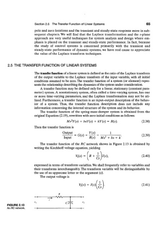
The transfer function of the RC network shown in Figure 2.13 is obtained by
writing the Kirchhoff voltage equation, yielding
V,{s) = ( R + ^ W), (2.40)
expressed in terms of transform variables. We shall frequently refer to variables and
their transforms interchangeably. The transform variable will be distinguishable by
the use of an uppercase letter or the argument (s).
The output voltage is
V (s) = Hs)[jA> (2.41)
2
R
-wv -o +
FIGURE 2.13
An RC network.