
Page 142 - Modern Control of DC-Based Power Systems
P. 142
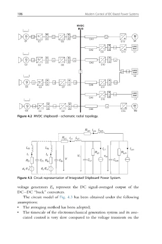
106                                 Modern Control of DC-Based Power Systems


                                          MVDC
                                           BUS
                          R      _ _  R                          _ _
              G      ~ ~ _ _  L   _ _  L                                M
               ~          C          C           CA1               ~ ~   ~
              G1     C1           C5                             C13    M1
                                                      _ _  R      _ _
                                                        _ _  L         LVAC
                                                CA2        C       ~ ~  load
                                                       C9         C14   L1
                          R      _ _  R                _ _  R
              G      ~ ~ _ _  L   _ _  L                _ _  L
               ~          C          C           CA3       C
              G2     C2           C6                   C10
                                                                        LVDC
                                                                        load
                                                                        L2
                          R      _ _  R                _ _  R
               G     ~ ~ _ _  L    _ _  L                  L
               ~          C           C         CA4     _ _  C
              G3      C3          C7                   C11
                                                      _ _  R
                                                        _ _  L         LVDC
                                                                        load
                                                           C
                                                CA5
                                                       C12              L3
                          R      _ _  R                           _ _
               G      ~ ~ _ _  L   _ _  L                               M
               ~          C           C                            ~ ~  ~
              G4      C4          C8            CA6               C15   M2
          Figure 4.2 MVDC shipboard—schematic radial topology.

                                              R cm I cm  L cm
                                  R c1 I  L
                                      c1  c1

               L f1      L fn                           I L1          I Lm
                                                   R L1          R Lm
               I 1       I n              V             v
                                    V      1             m
                      C         C               C            C
               R f1    f1 R fn   fn              c1           cm
             d ·E 1    d ·E n
              1
                        n
          Figure 4.3 Circuit representation of Integrated Shipboard Power System.

          voltage generators E n represent the DC signal-averaged output of the
          DC DC “buck” converters.
             The circuit model of Fig. 4.3 has been obtained under the following
          assumptions:
          •  The averaging method has been adopted;
          •  The timescale of the electromechanical generation system and its asso-
             ciated control is very slow compared to the voltage transients on the