Page 143 - Modern Control of DC-Based Power Systems
P. 143

Generation Side Control                                      107


                MVDC bus and therefore the output of this system can be considered
                constant during the period of observation;
             •  The generic generating system has been represented by DC ideal
                voltage DC sources E n (representing the buck converter output) with
                the duty cycle d connected to a second-order RLC filter, whose
                parameters are R fn ,L fn and C fn ;
             •  The zonal loads and single component loads and their characteristics
                can be lumped into an equivalent load which exhibits CPL
                characteristic;
             •  The generic load has been represented by a load branch resistor R Lm
                and a controlled current source I Lm 5 P m /V m ; these two branches
                represent the linear and the nonlinear (assumed as infinite bandwidth
                CPL) parts of the load;
             •  The generic lines which connect the loads to the MVDC bus
                are characterized by the lumped cable parameters R cm , L cm and by a
                possible input filtering capacitor C cm of the load converter.
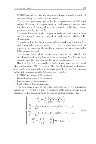
                 Based on Fig. 4.3 it is possible to derive a state-space average model
              of a multimachine MVDC system. The Kirchhoff current and voltage
              laws enable us to express the mathematical model by n 1 2m 1 1nonlinear
              differential equations with the following state variables:
             •  MVDC bus voltage, V (1 equation);
             •  Generators currents, I n (n equations);
             •  Line currents, I ch (m equations);
             •  Load voltages, V m (m equations).
                 The state-space model of the system presented in Fig. 4.3 is therefore
              defined in (4.1) by the n 1 2m 1 1 equations of the system, where a total
              capacitor C eq has been defined as the sum of all filter capacitors C fn :
                        8                                 !
                                               n      m
                                  dV     1   X      X
                                      5         I k 2
                        >
                        >
                        >                               I ch
                                   dt
                        >
                        >
                                              k51    h51
                        >               C eq
                        >
                        >
                        >
                        >
                           dI k
                        >        1
                        >     5      2 R fk I k 1 V 1 E k ’k 5 1; 2; .. . ; n
                        >
                           dt
                        >
                        <       L fk
                                                                          (4.1)
                                 1
                          dI ch
                              5
                        >
                        >           2 R ch I ch 1 V 2 V h Þ’h 5 1; 2; .. . ; m
                        >          ð
                        >  dt   L ch
                        >
                        >
                        >
                                                !
                        >
                        >
                        >            1
                             dV h             P h
                        >
                        >        5       I ch 2
                        >                         ’h 5 1; 2; .. . ; m
                              dt
                        >
                        :           C ch      V h
   138   139   140   141   142   143   144   145   146   147   148