
Page 144 - Modern Control of DC-Based Power Systems
P. 144
108 Modern Control of DC-Based Power Systems
I
L f1 L fn I lin I C
I 1 I n I CPL = P/V
V
R f1 R fn R lin C eq
d ·E 1 d ·E n
n
1
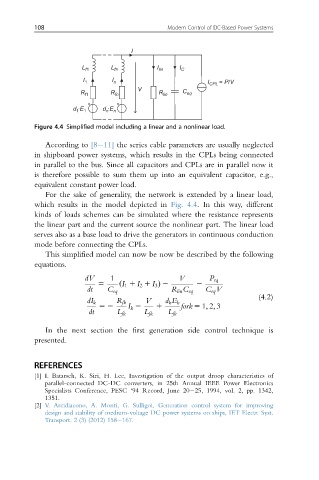
Figure 4.4 Simplified model including a linear and a nonlinear load.
According to [8 11] the series cable parameters are usually neglected
in shipboard power systems, which results in the CPLs being connected
in parallel to the bus. Since all capacitors and CPLs are in parallel now it
is therefore possible to sum them up into an equivalent capacitor, e.g.,
equivalent constant power load.
For the sake of generality, the network is extended by a linear load,
which results in the model depicted in Fig. 4.4. In this way, different
kinds of loads schemes can be simulated where the resistance represents
the linear part and the current source the nonlinear part. The linear load
serves also as a base load to drive the generators in continuous conduction
mode before connecting the CPLs.
This simplified model can now be now be described by the following
equations.
dV 1 V P eq
5 I 1 1 I 2 1 I 3 Þ 2 2
dt C eq ð R lin C eq C eq V
(4.2)
dI k R fk V d k E k
52 I k 2 1 fork 5 1; 2; 3
dt L fk L fk L fk
In the next section the first generation side control technique is
presented.
REFERENCES
[1] I. Batarseh, K. Siri, H. Lee, Investigation of the output droop characteristics of
parallel-connected DC-DC converters, in 25th Annual IEEE Power Electronics
Specialists Conference, PESC ‘94 Record, June 20 25, 1994, vol. 2, pp. 1342,
1351.
[2] V. Arcidiacono, A. Monti, G. Sulligoi, Generation control system for improving
design and stability of medium-voltage DC power systems on ships, IET Electr. Syst.
Transport. 2 (3) (2012) 158 167.