
Page 291 - Modern Control of DC-Based Power Systems
P. 291
250 Modern Control of DC-Based Power Systems
Ultimately, the advantages of the Hardware in the Loop can be sum-
marized by these points:
• Increased Safety
• Enhanced Quality
• Reduced Time.
In the general configuration, the HiL is composed by a digital simula-
tor, which performs in real time the simulation of the electrical power
system, the digital controllers, and the interfaces between the digital sim-
ulator and the hardware devices.
In the simulation test, the HiL testing platform is based on the follow-
ing components:
• A the real-time computer target which is a PC running an operating
system provided by National Instruments executing graphical user
interface with the possibility of changing the control parameters dur-
ing runtime.
• The FPGA target, a Xilinx Virtex5 LX-30 FPGA board, where the
control strategies are implemented.
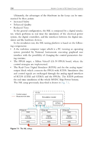
• The Real-Time Digital Simulator (RTDS) and the the analog input/
output block which connects the FPGA with RTDS. Simulation data
and control signals are exchanged through the analog signal interfaces
of RTDS (GTAI and GTAO) and the FPGAs. The RTDS performs
the real-time simulation of the whole MVDC Ship Power System.
The HiL setup previously described is shown in Fig. 7.1.
RTDS
Control output
Measurement data
Simulation model
GTAI GTAO
FPGA #1 FPGA #2 FPGA #3
DAC DAC DAC
Digital Digital Digital
controller controller controller
ADC ADC ADC
Figure 7.1 The HiL setup.