
Page 296 - Modern Control of DC-Based Power Systems
P. 296
Hardware In the Loop Implementation and Challenges 255
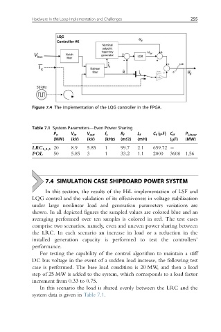
Figure 7.4 The implementation of the LQG controller in the FPGA.
Table 7.1 System Parameters—Even Power Sharing
P n V in V out f s R f L f C f (μF) C if P Linear
(MW) (kV) (kV) (kHz) (mΩ) (mH) (μF) (MW)
LRC 1,2,3 20 8.9 5.85 1 99.7 2.1 659.72
POL 50 5.85 3 1 33.2 1.1 2000 3608 1,56
7.4 SIMULATION CASE SHIPBOARD POWER SYSTEM
In this section, the results of the HiL implementation of LSF and
LQG control and the validation of its effectiveness in voltage stabilization
under large nonlinear load and generation parameters variations are
shown. In all depicted figures the sampled values are colored blue and an
averaging performed over ten samples is colored in red. The test cases
comprise two scenarios, namely, even and uneven power sharing between
the LRC. In each scenario an increase in load or a reduction in the
installed generation capacity is performed to test the controllers’
performance.
For testing the capability of the control algorithm to maintain a stiff
DC bus voltage in the event of a sudden load increase, the following test
case is performed. The base load condition is 20 MW, and then a load
step of 25 MW is added to the system, which corresponds to a load factor
increment from 0.33 to 0.75.
In this scenario the load is shared evenly between the LRC and the
system data is given in Table 7.1.