
Page 299 - Modern Control of DC-Based Power Systems
P. 299
258 Modern Control of DC-Based Power Systems
disconnection of LRC 3 .In Fig. 7.7 it is seen that the response has a faster
settling time and the peak to peak oscillation is larger than in the load
connection case. The reason for the faster settling time lies in the load
factor which is 0.5, smaller compared to 0.66 load factor in the step
increase test case.
The LSF exhibits, in Fig. 7.8, a transient behavior which is less
smooth than during the step increase. The reason is that the compensa-
tion and linearization of the nonlinearity was split over three converters
but only two converters need to fulfill the task without an update of their
compensation coefficients. This shows a remarkable result in term of
robustness that such a drastic change from the model assumption can be
withstood by the LSF. Similar to Fig. 7.6, also in Fig. 7.8 an oscillation
can be detected that remains in steady state but is bounded to
6 0:2280 kV which is equal to 3.986% of the averaged steady-state
value. The system under the control of the LSF is consequently BIBO
stable.
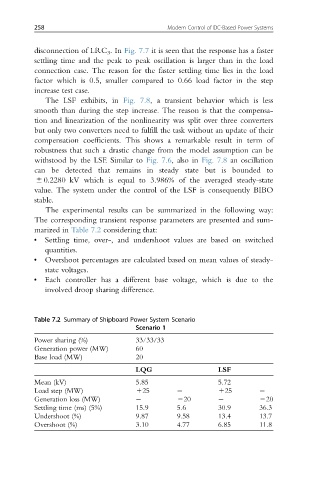
The experimental results can be summarized in the following way:
The corresponding transient response parameters are presented and sum-
marized in Table 7.2 considering that:
• Settling time, over-, and undershoot values are based on switched
quantities.
• Overshoot percentages are calculated based on mean values of steady-
state voltages.
• Each controller has a different base voltage, which is due to the
involved droop sharing difference.
Table 7.2 Summary of Shipboard Power System Scenario
Scenario 1
Power sharing (%) 33/33/33
Generation power (MW) 60
Base load (MW) 20
LQG LSF
Mean (kV) 5.85 5.72
Load step (MW) 125 125
Generation loss (MW) 220 220
Settling time (ms) (5%) 15.9 5.6 30.9 36.3
Undershoot (%) 9.87 9.58 13.4 13.7
Overshoot (%) 3.10 4.77 6.85 11.8