
Page 295 - Modern Control of DC-Based Power Systems
P. 295
254 Modern Control of DC-Based Power Systems
FPGA #1
LQG
V bus
controller
I 1
RTDS
V bus
FPGA #2 U 1
LQG U 2 Plant
V bus Moving
average
controller
I 2 (100 µs) Moving
5 µs
U 3 I k I k
average
(100 µs)
FPGA #3
V bus
LQG
controller
I 3
Signal generator
50 kHz
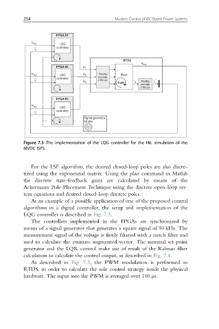
Figure 7.3 The implementation of the LQG controller for the HiL simulation of the
MVDC ISPS.
For the LSF algorithm, the desired closed-loop poles are also discre-
tized using the exponential matrix. Using the place command in Matlab
the discrete state-feedback gains are calculated by means of the
Ackermann Pole-Placement Technique using the discrete open-loop sys-
tem equations and desired closed-loop discrete poles.
As an example of a possible application of one of the proposed control
algorithms in a digital controller, the setup and implementation of the
LQG controller is described in Fig. 7.3.
The controllers implemented in the FPGAs are synchronized by
means of a signal generator that generates a square signal of 50 kHz. The
measurement signal of the voltage is firstly filtered with a notch filter and
used to calculate the estimate augmented vector. The nominal set-point
generator and the LQR control make use of result of the Kalman filter
calculation to calculate the control output, as described in Fig. 7.4.
As described in Fig. 7.3, the PWM modulation is performed in
RTDS, in order to calculate the sole control strategy inside the physical
hardware. The input into the PWM is averaged over 100 μs.