
Page 297 - Modern Control of DC-Based Power Systems
P. 297
256 Modern Control of DC-Based Power Systems
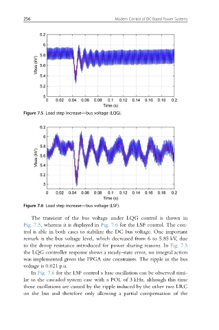
Figure 7.5 Load step increase—bus voltage (LQG).
Figure 7.6 Load step increase—bus voltage (LSF).
The transient of the bus voltage under LQG control is shown in
Fig. 7.5, whereas it is displayed in Fig. 7.6 for the LSF control. The con-
trol is able in both cases to stabilize the DC bus voltage. One important
remark is the bus voltage level, which decreased from 6 to 5.85 kV, due
to the droop resistance introduced for power sharing reasons. In Fig. 7.5
the LQG controller response shows a steady-state error, no integral action
was implemented given the FPGA size constraints. The ripple in the bus
voltage is 0.021 p.u.
In Fig. 7.6 for the LSF control a base oscillation can be observed simi-
lar to the cascaded system case with a POL of 3 kHz, although this time
those oscillations are caused by the ripple induced by the other two LRC
on the bus and therefore only allowing a partial compensation of the