
Page 298 - Modern Control of DC-Based Power Systems
P. 298
Hardware In the Loop Implementation and Challenges 257
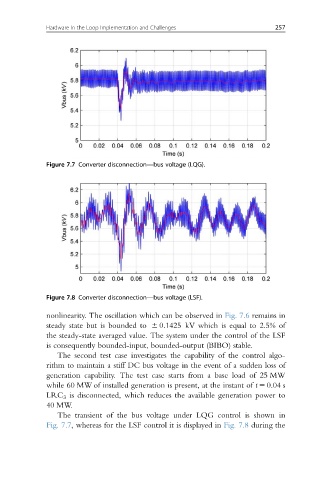
Figure 7.7 Converter disconnection—bus voltage (LQG).
Figure 7.8 Converter disconnection—bus voltage (LSF).
nonlinearity. The oscillation which can be observed in Fig. 7.6 remains in
steady state but is bounded to 6 0:1425 kV which is equal to 2.5% of
the steady-state averaged value. The system under the control of the LSF
is consequently bounded-input, bounded-output (BIBO) stable.
The second test case investigates the capability of the control algo-
rithm to maintain a stiff DC bus voltage in the event of a sudden loss of
generation capability. The test case starts from a base load of 25 MW
while 60 MW of installed generation is present, at the instant of t 5 0.04 s
LRC 3 is disconnected, which reduces the available generation power to
40 MW.
The transient of the bus voltage under LQG control is shown in
Fig. 7.7, whereas for the LSF control it is displayed in Fig. 7.8 during the