
Page 96 - Modern Control of DC-Based Power Systems
P. 96
60 Modern Control of DC-Based Power Systems
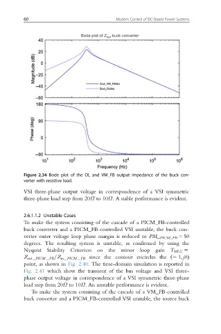
Figure 2.34 Bode plot of the OL and VM_FB output impedance of the buck con-
verter with resistive load.
VSI three-phase output voltage in correspondence of a VSI symmetric
three-phase load step from 20Ω to 10Ω: A stable performance is evident.
2.6.1.1.2 Unstable Cases
To make the system consisting of the cascade of a PICM_FB-controlled
buck converter and a PICM_FB-controlled VSI unstable, the buck con-
verter outer voltage loop phase margin is reduced to PM_ PICM_FB 5 50
degrees. The resulting system is unstable, as confirmed by using the
Nyquist Stability Criterion on the minor loop gain T MLG 5
Z out PICM FB =Z in PICM FB since the contour encircles the ð2 1; j0Þ
point, as shown in Fig. 2.40. The time-domain simulation is reported in
Fig. 2.41 which show the transient of the bus voltage and VSI three-
phase output voltage in correspondence of a VSI symmetric three-phase
load step from 20Ω to 10Ω. An unstable performance is evident.
To make the system consisting of the cascade of a VM_FB-controlled
buck converter and a PICM_FB-controlled VSI unstable, the source buck